-

- Joined:
- Apr 27, 2017
- 3
- 0
- 0
- Location:
- Edmonton
- Vehicle:
- 2013 Prius v wagon
- Model:
- Five
Hello Everyone,
Posting here for the 1st time and i hope i can get some help. I have a 2013 Prius V. At around 374,000 km’s, the head gasket blew. After doing some detailed research i was able to order a new engine with only 16000 kms, and installed it myself. I removed everything and installed it back without breaking anything. The good news is that my car runs like brand new and there are no issues with the engine.
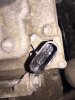
The problem is that i happen to spill some coolant on the A/C compressor communication port (Pic included) in the process. I did not notice that port being wet when i was plugging everything back. After putting everything back and restarting my car, it gave me 2 codes — ‘B1498 Communication Malfunction (A/C Inverter Local)’ and ‘ P0AA6 Hybrid/EV battery Voltage system isolation fault’.
I took it to the dealer to have it diagnosed and also have them check how my DIY on engine change went. They came back to me saying «you did a perfect job» except you need a new A/C compressor to fix those 2 codes. For which they quoted me $5500 CAD for. Obviously i was not going to pay that kind of money and got lucky to find a used A/C compressor for $100. After installing this compressor with working communication port, the P0AA6 code went away and there are no signs on the dash.
The issue that still remains is with the B1498 Communication Malfunction code. From what i understand, the comm port on A/C compressor got water damaged completely which also triggered the P0AA6 code, but with the new compressor P0AA6 code went away. But it seems like there is still some issue on the harness side or whereever this harness goes which is still giving me the B1498 code. BTW the A/C compressor doesn’t come alive when i turn the AC on.
Thank you in advance,
Deep -
The compressor receives an inverter control signal from the power management ECU. I am guessing this is the communication malfunction you are experiencing. The ECU talks to the A/C amplifier assembly for data input. Check those connections and also confirm that the coolant is completely cleaned from the comm port.
-
- Joined:
- Apr 27, 2017
- 3
- 0
- 0
- Location:
- Edmonton
- Vehicle:
- 2013 Prius v wagon
- Model:
- Five
Thanks for the reply. The ports are completely dry, that is for sure. I checked the wiring harness for continuity using a multimeter and the wiring harness is good. The wiring harness from AC compressor ends in the fuse box, which is where i performed the test.
What should my next step be? Which connections are you mentioning ? Where is the ECU and AC amplifier.
I really appreciate anyone helping me out on this. Thank you.
-
- Joined:
- Apr 27, 2017
- 3
- 0
- 0
- Location:
- Edmonton
- Vehicle:
- 2013 Prius v wagon
- Model:
- Five
This is the port i am referring to on the AC compressor that i dropped coolant in. I have changed the AC compressor since. But i am still getting B1498 code. Check my above posts for more info.
Thank you
Attached Files:
-
VintageGold
Junior Member- Joined:
- May 16, 2018
- 28
- 14
- 7
- Location:
- Utah
- Vehicle:
- 2012 Prius
- Model:
- Four
I know this thread is old but were you ever able to resolve your issue? I had my engine replaced recently and I’m getting this code now.
-
- Joined:
- Oct 20, 2011
- 123
- 52
- 0
- Location:
- Sunnyvale, CA
- Vehicle:
- 2012 Prius v wagon
- Model:
- Five
Well, this is now another person wondering about this code…. I did a head job and during that, some coolant briefly dropped into the control connector of the A/C compressor. Now I have a 1498 error too. I never had that before. I wouldn’t think that having fluid temporarily drop into the connector would cause a problem. They are usually sealed and I definitely cleaned everything out and ensured it was dry before reassembly. But now the compressor turns on for a bit and then turns off and throws the B1498 error.
Does anyone know a way to fix this? What is the problem? Did the internal inverter board somehow get fried?
-
- Joined:
- Jan 8, 2017
- 2,515
- 3,237
- 9
- Location:
- California
- Vehicle:
- 2016 Prius
- Model:
- Three Touring
If the connector was disconnected when the spill occurred, there could be coolant residue on the connector housing, terminals, or inside the unit, causing a poor connection or intermittent terminal-to-terminal or terminal-to-ground faults. Before replacing any expensive parts, try throughly cleaning the connector.
You could also try steps 1 through 5 of the troubleshooting procedure for DTC B1498/98 in the Air Conditioning System section of the Repair Manual (more info). This procedure includes checks for CAN or hybrid control system DTCs and for wire harness faults.
-
- Joined:
- Oct 20, 2011
- 123
- 52
- 0
- Location:
- Sunnyvale, CA
- Vehicle:
- 2012 Prius v wagon
- Model:
- Five
Thank you for the response Elktroingenie…. I really do appreciate your taking the time you took to add some ideas….
I immediately removed the coolant that splashed in there and blew it clean. Two weeks passed while I was doing my head job, and then everything went back together. With about 2000 miles on the car, it started to get warm outside and that is when the A/C issue cropped up. I went back and confirmed all connections and did take an extra step of thoroughly cleaning the connection. I used an electronics aerosol on both the compressor and the connector, and lightly drew a needle file across the pins to break any crud that could have been there. The problem remained, but I really think the connection is fine now. I also opened the connector on the wire side to see if there were any crushed wires; there were none.
I do have a little more information though. I’ve been trying to correlate what might trigger the problem or be related. This morning (very cool), the A/C worked perfect and the sight glass shows proper level (that was confirmed by an independent shop, by the way… they said there is no leaks and it is all charged). I jostled the wires around to see if there was a position where everything stopped… Again, no problems; it blew fine.
Now the observation. Yesterday when it was hot, I noticed that the pump was on when the fans were on, and the opposite was also true. As soon as the fans stopped, the pump stopped (or shortly thereafter). This morning it was very cold and the fans were on the whole time the pump was on (after 5 minutes of having it on, I gave up… never did fail). Part of me is wondering if I’m on a wild goose chase. Maybe this B1498 (which I’ve not seen on my cheesy FixD OBD reader, the independent shop told me about that… oh, and yes, I’m getting a better reader) is tangential. Maybe the lack of a fan causes the pump to heat up and go into a thermal shutdown. That would then cause the communications to stop and, therefore, the B1498. I’m wondering if that is possible… Thoughts?
I do know that this morning, the vertical aluminum bulb that is in the compressor line (not sure what this is… an expansion chamber) was *very* warm, along with the pump. But this morning, all of that was very cool. Now, it is true that the temperature outside was warm and it was, as stated, cool out this morning, but the mechanical compressing of the freon will generate a lot of heat. If the evaporator coil isn’t getting air drawn through it to cool the freon down, then that heat is going to stay in the system.
Assuming this seems like a plausible scenario, I’d love to hear how one might diagnose the root cause of why the fans would not come on when the A/C pump is on. Sadly, I suspect the opposite is also true though. The ECU may shut the fans off if it detects a communications issue (B1498). I am aware that this whole vein of thought has two avenues of what is affecting what.

P.S. Thank you for the suggestion on the diagnosis steps and such. I became aware of the temporary TIS subscription just recently and I very well will try that route. Because it is time limited, I need to be sure I’ll have a block of time to make use of the resource before it expires. But that is on the agenda if I cannot otherwise figure this thing out.
-
- Joined:
- Oct 20, 2011
- 123
- 52
- 0
- Location:
- Sunnyvale, CA
- Vehicle:
- 2012 Prius v wagon
- Model:
- Five
Slight update…. I’m working at home for my real job now, which gives me the opportunity to run out between meetings and to see if I can draw some conclusions about when the A/C works and when it does not…..
As I mentioned before, the compressor worked perfectly this morning when it was very cold. As such, I was very curious to see what would happen as the weather started to warm up. Sure enough, I pressed ON and the the engine, fans and A/C all came on. Eventually, the engine turned off (normal) and the radiator fans continued to run, as did the AC compressor. I could see fluid passing the sight glass and the low side was crispy cold…
And then….. The fans turned off! I could immediately hear the compressor turn off, and a visual inspection of the sight glass no longer showed fluid moving past. For a very brief moment, the fans came on again (and the fluid flowed in the sight glass), then the fans turn off, yada yada yada.
So, the conclusion is that when the fans are on, the pump is on. What I don’t know is which behavior is causing no A/C. Is it an issue with the A/C compressor (B1498?) that turns off the compressor *and* thus the fans? Or is it the fans turning off for some reason that causes the ECU to say «wow! we don’t run the A/C without the fans running, so I’m turning off the compressor»…. Or, is there some electrical issue (relay, wiring, etc) which is influencing/causing all of this?
I can say that I’ve moved the wires around along the length of the harness to feel pretty confident in saying that I don’t think there is an issue with the wiring (yes, I know this is not definitive and I will eventually check the continuity when I get time and if there is no other resolution).
Again, one final consideration here that I mentioned before. I have not personally seen the B1498 error. Further, when I press REC plus AUTO and START (no foot on brake), I get a flashing ’00’ on the temperature temp control. I understand that this means I have *no* codes. I was only told about the B1498 by a competent independent mechanic to whom I gave the car in an attempt to resolve the A/C issue. He eventually said that he could not figure out what was going on, but he was confident that the pump was working (although that doesn’t mean there isn’t an intermittent issue in the pump’s inverter control board) and, more importantly, that the system was charged and not leaking. But the point is that I don’t want to draw too much focus on the B1498. I think that my last scenario where a thermal overload within the pump could very well be true….
So, that is about it for now…. I am curious to hear if it is normal for the A/C to come on/off (as well as the fans) when the A/C is set to AUTO and LO. What I’m getting at here is… Maybe I really did have a connector issue and I’ve resolved that, and now the system is just behaving normally? I’ve owned the car since new (10 years), but I’ve never paid attention to the nuances of the A/C compressor.
-
VintageGold
Junior Member- Joined:
- May 16, 2018
- 28
- 14
- 7
- Location:
- Utah
- Vehicle:
- 2012 Prius
- Model:
- Four
Man, I did that thing that drives me crazy: people find a solution and don’t post back about it.
Sorry about that.
In my case, the compressor didn’t work at all and it had to be replaced. At the time (Aug 2018), it was about $125.
-
- Joined:
- Oct 20, 2011
- 123
- 52
- 0
- Location:
- Sunnyvale, CA
- Vehicle:
- 2012 Prius v wagon
- Model:
- Five
Thanks for posting!
Man, if I could a compressor replaced for $125 I’d do it just to see if it worked. But the compressor now is about $1300 (new…. $500 remanufactured, $150 as a gamble from a junk yard), $300 for Toyota’s oil, and about $40 for an equivalent, and about $125 for the charging of the system. That adds up to enough that I want to be sure I really need to replace it first.
-
Ah. Yes, that can be normal behavior. It’s more normal when set for AUTO and a temperature than when set for AUTO and LO, though.
The compressor is variable speed. Depending on how hot it is outside and how much cooling you’re asking for, if you have a scan tool to watch the «AC watts» parameter, you could see the compressor running at over two thousand watts full out, all the way down to maybe 250 or 300 watts when only a little cooling is needed. If less cooling is needed than that, it will cycle off and on (so, between 0 watts and 350, 450 or so).
If the fans aren’t needed for engine or inverter cooling, they will also cycle off when the compressor does.
I am a little more puzzled that the compressor would be cycling off when the temp is set for LO. But this could happen if the evaporator temperature (another parameter you can watch with a scan tool) gets down to the range for potential icing, or if the liquid-line pressure (another watchable one!) goes out of bounds.
-
- Joined:
- Oct 20, 2011
- 123
- 52
- 0
- Location:
- Sunnyvale, CA
- Vehicle:
- 2012 Prius v wagon
- Model:
- Five
Fantastic information, Chapman. Thank you!
I don’t have a scan tool, unfortunately, but I do have one on order. Because I’m not a professional mechanic, I cannot really justify a commercial grade unit. I currently have a FixD type which is completely inadequate for higher level stuff like what we are talking about. However, it works *really* well for increasing confidence for when my daughter or wife are using the car. They know/care little about mechanics, and if the service light goes on, this way it will immediately alert me wherever I am. I can see it and tell them that they really do need to get off the road because the water pump failed (type of thing).I have an OBDLink MX+ on order, and it should be here in a few days. That should allow me to do some ‘live’ testing as you are suggesting. This is actually where I am going with it all too. I think I may really have had a poor connection in the connector before, but everything might be working perfectly now. My wife drove the car to school yesterday with LO and full fan. On the trip to school, the A/C was on and cranking cold air like there was no tomorrow; that trip was about 13 minutes. On the way back, however, the A/C stopped and she had to open the windows. That still doesn’t feel «correct» to me, but I do have to note that the car was in ECO mode too. I have learned that this can affect the A/C compressor «on» times too.
I have yet to see the B1498 myself. I suspect the FixD is not capable of showing those, and my other OBD units are all pretty sketchy. The MX+ will hopefully resolve that hole. But I *would* expect a 14 and 98 to show up on the temperature display, assuming the REC + AUTO trick works on a 2012 Prius V heating system.
-
As I understand it, ECO mode puts a cap on the top power the A/C will run at. So in ECO mode, instead of running flat out under high demand, it will run up to around two thousand watts or so. I don’t think ECO mode does anything directly with cycle times.You shouldn’t expect a 14 and a 98, just a 98.
The display shows two-digit abbreviated versions of DTCs. For the HVAC, they all happen to be the xy digits of a corresponding B14xy DTC (I think). So if you ever saw a 14 and a 98, that would mean you also had a B1414 code (which isn’t a thing … at least in my Gen 3 liftback manual).One thing not to get too excited over, if you ever see it, is 21 (B1421) … that just means there’s not much light shining on the dash top photosensor at the time you ask for codes.
Be thankful you’re not working on one of the other systems, like the brakes, where the two digit abbreviations are not just the last two of the DTC, or sometimes are and sometimes aren’t (like C1336 has blink code 98)!
Reading parameters like liquid pressure, AC watts, and so on, doesn’t necessarily take a fancy scan tool, just one that you can teach the corresponding PIDs to. The smartphone app Torque is an example. You can find files with the Prius-specific PIDs in Torque’s import format.
-
- Joined:
- Oct 20, 2011
- 123
- 52
- 0
- Location:
- Sunnyvale, CA
- Vehicle:
- 2012 Prius v wagon
- Model:
- Five
Thanks for the info on the expected digit display on the temp control. I had assumed that I’d see a fast flash of 14 and 98, then a long pause, repeat. But it makes sense that that they’d leave off the 14, I guess. At any rate, all I’ve seen is 00. I don’t know if/how those codes get reset through the approach we are discussing for viewing. Maybe it is just when you turn the car off again?
I think you can get Torque to work on the FixD, but I don’t have that app yet. It is good to know that a fairly inexpensive OBD will work with a more capable program though. I’ve gone through my share of ELM type OBD and I’m pretty fed up with them. Some may work fine, but I’ve not had good luck. This is why I bit the bullet and decided to get a MX+. They seem to have a fairly decent set of reviews on different sites, and at least I’m buying something from a «real» company. Most of the ELM guys are all weakly rebranded products from some shop in China for which there is no/little traceability. Been there, done that….
-
- Joined:
- Jul 17, 2018
- 1,618
- 531
- 3
- Location:
- SE Texas
- Vehicle:
- 2011 Nissan LEAF
- Model:
- —-USA—-
Tech stream with cable. Check ebay.
It the toy software toy dealerships use. Under $50 -
- Joined:
- Oct 20, 2011
- 123
- 52
- 0
- Location:
- Sunnyvale, CA
- Vehicle:
- 2012 Prius v wagon
- Model:
- Five
I wanted to give a quick update….checked for broken wires and could find none. After cleaning the contacts, things worked better, and that is a tell. Given this experience, and that of the original poster to this thread, I have come to what I believe is the likely problem.
The compressor is actually a neat device. It has a variable frequency drive (VFD) board inside it so that the ECU can control the amount of power being used by the compressor. That is cool, but the problem is that the idiots at Denso appear to have used a connector that doesn’t have the pins molded into the plastic (my theory). In addition, the connector is upwards facing. This means that *any* fluid that happens to drop on the connector can leak into the top part of the compressor where the VFD is located. That is an inexcusable weak point, in my honest opinion. Sure, you shouldn’t be splashing coolant around, but you also build something with a defensive posture in mind (or you should).
Anyhow, I believe that coolant is not a very good dielectric and I suspect that even a small amount of coolant will drop onto the board and cause issues. Now comes the interesting thing… How to fix this (again, assuming I’m right).
The *best* solution would be to remove the top cover and you could easily clean the board. Unfortunately, although the VFD board is clearly not pressurized, the connections to the 3 phase motor have a rubber seal around them that press against the board. Without having taken a compressor apart, I am guessing that when you take off the cover, you’ll relax the pressing of that seal, and all your R134a will quickly escape (and cause havoc on the environment, so don’t do it!). So, the only option is to try to dilute/clean the board by introducing more fluid. Therein lies the conundrum. The best thing to do is to use a PCB or contact cleaner. But these are high VOC fluids, which means that they are flammable. Because they are being introduce into a closed cavity, they likely won’t flash off very much, so the VOCs will remain. Technically this could even be a tiny bomb if you filled the thing up; however, I’m guessing we are talking about literally a tiny drop, which I seriously doubt could blow off the cover at all (worst case scenario).
Probably the best thing would be to evacuate the system, remove the cover (spoiler: you need to figure out how to remove the special bolts), clean everything, reassembly and then charge again. But, the reality is that I’m not even positive that the fluid can leak through the pins. Therefore, I went ahead with the «fill the connector with contact cleaner, wait 10 seconds, then gently blow out the remaining fluid into a ran (careful… don’t want it in your eyes, etc). At the very least, this helped clean the contacts (I also used a tiny file to draw across the pins… not to file but to break any corrosion that might be there). If the pins are embedded, then nothing got into the cavity. If not, then a tiny amount did. And, if by chance my compressor fries, well, I’ll have to get a new one and recharge anyhow. There isn’t a huge downside to the experiment.
So, what are the results? So far, the car seems to no longer have an issue with the AC. It hasn’t been driven extensively, and the weather has gotten a lot cooler more recently so the need for AC has been reduced. But, while I was using the AC, it didn’t stop at all. Previously, I would run into problems within 15 to 30 seconds (or the compressor wouldn’t even come on). Is this success then? I don’t know… ONly time will tell.
Finally, there is near zero information out there about the Denso pumps. There is a single, and interesting, video of a guy taking apart a Denso AC pump on YouTube but, sadly, he doesn’t really show much of the VFD board.
Full disclosure: I am an amateur and a flaming idiot. Don’t trust anything I say or use this as a recommendation… If you decide to review my thoughts and take action on them, you do so at your own risk. I assume absolutely no responsibility or liability. I’m just an amateur bloke that is postulating how some of this MIGHT work.
-
I am pretty sure there’s a thread here where somebody worked on that. If I remember right, there was frustration involved with the slack available between the connector and board, or board and motor, or something; anyway, a challenge to usefully disassembling without cutting or desoldering something.
Sometimes, another pair of eyes can help. After all, they had to have a way of assembling the thing.


DTC
B1498/98 Communication Malfunction (A/C Inverter Local)
for Preparation Click here
DESCRIPTION
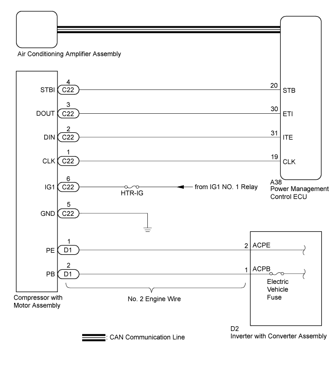
The power management control ECU and compressor with motor assembly transmit information to one another via a communication line. Compressor control is stopped and the DTC is stored if communication information is cut off or abnormal information occurs.
The DTC is also detected if high-voltage power supplied from the inverter with converter assembly to the compressor control circuit is shut off.
The DTC will be stored as a history DTC.
| DTC No. | DTC Detection Condition | Trouble Area |
| B1498/98 |
|
|
WIRING DIAGRAM
INSPECTION PROCEDURE
- CAUTION:
- Wear insulated gloves and pull out the service plug grip before inspection as procedures may require disconnecting high-voltage connectors. Carry the removed service plug in your pocket to prevent other technicians from accidentally reconnecting it while you are servicing the vehicle.
- Do not touch the high-voltage connectors or terminals for 10 minutes after the service plug grip is removed.
- NOTICE:
- Inspect the fuses for circuits related to this system before performing the following inspection procedure.
- After turning the ignition switch off, waiting time may be required before disconnecting the cable from the negative (-) auxiliary battery terminal. Therefore, make sure to read the disconnecting the cable from the negative (-) auxiliary battery terminal notices before proceeding with work (Click here).
- The hybrid control system and air conditioning system output DTCs separately. Inspect DTCs following the diagnosis procedure for the hybrid control system first if any DTCs from those systems are output simultaneously.
- Depending on the timing of the power supply to the 12 V power supply circuit and high-voltage circuit when the ignition switch is ON (READY), an abnormal information signal may be output, causing this DTC to be stored. If the output DTC is a code that was memorized in the past, check the fuses and wire harnesses. If there is no malfunction, clear the DTC.
1.CHECK CAN COMMUNICATION SYSTEM
-
Use the Techstream to check if the CAN communication system is functioning normally.
- Result:
-
Result Proceed to CAN DTC is not output A CAN DTC is output B
|
||||
| A | |
2.CHECK DIAGNOSTIC TROUBLE CODE
-
Check if DTCs for the hybrid control system are output using the Techstream.
- Result:
-
Result Proceed to DTC is not output A Only DTC P3108 is output A DTCs other than P3108 are output B
|
||||
| A | |
3.CHECK HARNESS AND CONNECTOR (COMPRESSOR WITH MOTOR ASSEMBLY — BODY GROUND)
- CAUTION:
- Do not disconnect the connector on the high-voltage side.
-
Disconnect the C22 compressor with motor assembly connector.
-
Measure the resistance according to the value(s) in the table below.
- Standard Resistance:
-
Tester Connection Condition Specified Condition C22-5 (GND) — Body ground Always Below 1 Ω
|
REPAIR OR REPLACE HARNESS OR CONNECTOR |
|||
| OK | |
4.CHECK HARNESS AND CONNECTOR (COMPRESSOR WITH MOTOR ASSEMBLY — IG CIRCUIT, GROUND)
-
Turn the ignition switch to ON (IG).
-
Measure the voltage according to the value(s) in the table below.
- Standard Voltage:
-
Tester Connection Condition Specified Condition C22-6 (IG1) — C22-5 (GND) Ignition switch ON (IG) 11 to 14 V C22-6 (IG1) — C22-5 (GND) Ignition switch off Below 1 V
|
REPAIR OR REPLACE HARNESS OR CONNECTOR |
|||
| OK | |
5.CHECK HARNESS AND CONNECTOR (POWER MANAGEMENT CONTROL ECU — COMPRESSOR WITH MOTOR ASSEMBLY)
-
Disconnect the A38 power management control ECU connector.
-
Measure the resistance according to the value(s) in the table below.
- Standard Resistance:
-
Tester Connection Condition Specified Condition C22-1 (CLK) — A38-19 (CLK) Always Below 1 Ω C22-2 (DIN) — A38-31 (ITE) Always Below 1 Ω C22-3 (DOUT) — A38-30 (ETI) Always Below 1 Ω C22-1 (CLK) — Body ground Always 10 kΩ or higher C22-2 (DIN) — Body ground Always 10 kΩ or higher C22-3 (DOUT) — Body ground Always 10 kΩ or higher
|
REPAIR OR REPLACE HARNESS OR CONNECTOR |
|||
| OK | |
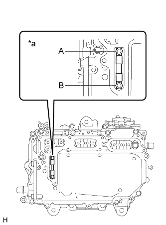
6.INSPECT ELECTRIC VEHICLE FUSE
- CAUTION:
- Be sure to wear insulated gloves.
-
Turn the ignition switch off.
-
Remove the service plug grip (Click here).
- CAUTION:
- Do not touch the high-voltage connectors or terminals for 10 minutes after the service plug grip is removed.
- NOTICE:
- After removing the service plug grip, turning the ignition switch to ON (READY) may cause a malfunction. Do not turn the ignition switch to ON (READY) with the service plug grip removed.
-
Remove the connector cover assembly (Click here).
- NOTICE:
- Be sure to prevent foreign matter or water from entering the inverter with converter assembly.
-
Check that bolts A and B are tightened securely.
-
Measure the resistance according to the value(s) in the table below.
- Standard Resistance:
-
Tester Item
(Tester Connection)Condition Specified Condition Electric vehicle fuse
(A — B)Always Below 1 Ω
Text in Illustration
*a Electric Vehicle Fuse
|
||||
| OK | |
7.INSPECT NO. 2 ENGINE WIRE
- CAUTION:
- Be sure to wear insulated gloves.
-
Disconnect the No. 2 engine wire connector (Click here).
-
Measure the resistance according to the value(s) in the table below.
- Standard Resistance:
-
Tester Connection Condition Specified Condition D1-1 (PE) — D2-2 (ACPE) Always Below 1 Ω D1-2 (PB) — D2-1 (ACPB) Always Below 1 Ω D1-1 (PE) — Body ground Always 10 kΩ or higher D1-2 (PB) — Body ground Always 10 kΩ or higher
|
||||
| OK | |
8.REPLACE COMPRESSOR WITH MOTOR ASSEMBLY
-
Replace the compressor with motor assembly (Click here).
- HINT:
- Since the compressor with motor assembly cannot be inspected while it is removed from the vehicle, replace the compressor with motor assembly with a new or known good one and check that the condition returns to normal.
-
Check for the DTC.
- Result:
-
Result Proceed to DTC B1498/98 is not output A DTC B1498/98 is output B
|
||||
| A | |
|
END (COMPRESSOR WITH MOTOR ASSEMBLY WAS DEFECTIVE) |
![]()
просит проверить гибридную систему
(1 чел.) (1) гость
|
Ну понятно!))) |
|
|
fermer написал: maslyakr написал: fermer написал: maslyakr написал:
1.А какой нибудь может кроме Тойоты считать??
Течстрим и шнурок. Сделал скан тойота-центре, как я и думал подкод 526((( После этого, скинул разъем с кондера — ошибка висит. отключил контакты с инвертора — ошибка ушла!!))
С 526 подкодом без хорошего мегомметра проблему не найти подскажите а где искать эту нижнюю крышку? помыл подкапотку загорелся чек по гибриду. пишет ошибку нет связи батареи с инвертором. не может чек загорется из за подушек безопастности? просто перед тем как мыл мотор вставлял потолочную подушку вместо стрельнувшей. краш в блоке подушек тоже ошибкой |
|

|
забыл написать приус с у меня |
|
|
xhunter написал: забыл написать приус с у меня В каком кузове Приус? |
|
|
с уважением, Сергей Николаевич. |
|
Nhp10 вроде так называется. С ИЛИ АКВА У японцев. 2015 год |
|
|
P3107 пишет ошибку. В1906 и в1698. А по гибоиду больше ошибок нет |
|
|
|
|
xhunter написал: P3107 пишет ошибку. В1906 и в1698. А по гибоиду больше ошибок нет
А где ошибка, что нет связи ввб с инвертором, как вы пишете? |
|
|
с уважением, Сергей Николаевич.
|

|
Так связи нет как я понял за подушек. Просто диагностику мне друг делает а он по мерсам спец. Сейчас сняли блок подушек что бы краш стереть. Мне интересно как вы писали выше куда могла после мойки мотора попасть вода? Какую крышку снять надо? Просто чек появился после мойки двигателя. |
|
|
Читая различные форумы по гибридам убеждаюсь что надо очень осторожно относиться к мойке под капотом высоким давлением,через раз проблемы после этого. |
|
|
Мойка ДВС это понты. За понт нужно платить. |
|
|
xhunter написал: Так связи нет как я понял за подушек. Просто диагностику мне друг делает а он по мерсам спец. Сейчас сняли блок подушек что бы краш стереть. Мне интересно как вы писали выше куда могла после мойки мотора попасть вода? Какую крышку снять надо? Просто чек появился после мойки двигателя.
Ошибки по Мерседесам и по Приусам в большинстве случаев обозначают совершенно разные проблемы |
|
|
с уважением, Сергей Николаевич. |

|
оказалась мойка не причем. чек загорелся из-за подушек как я только вставил новую подушку вместо стреляной. Оказалось надо было стереть краш в основном блоке подушек. |
|
|
Отогнал машину на диагностику, печка заработала,замёрзла видимо, всё равно пусть посмотрят. |
|
|
Здравствуйте. Prius 30 ошибка P0ADC не удаляется, для проверки делали замену HV батареи, блока реле, блока контроля температуры напряжения и тока HV батареи, проверили проводку от блока управления питанием до блока реле — все в порядке. Подкидывали инвертер, блок управления питанием. Результата нет. В прилагаемом файле данные fteeze frame и data stream неисправного автомобиля. Подскажите дальнейшие действия. |
|
|
Не получается вложить файл, подскажите пожалуйста как это сделать. Переименовал расширение в bmp. Для просмотра замените на tse. |
|
|
kostya-blg написал: Здравствуйте. Prius 30 ошибка P0ADC не удаляется, для проверки делали замену HV батареи, блока реле, блока контроля температуры напряжения и тока HV батареи, проверили проводку от блока управления питанием до блока реле — все в порядке. Подкидывали инвертер, блок управления питанием. Результата нет. В прилагаемом файле данные fteeze frame и data stream неисправного автомобиля. Подскажите дальнейшие действия. Машина при этом заводится или нет? |
|
|
с уважением, Сергей Николаевич. |
|
Нет, на дисплее сообщение …Проверьте гибридную систему.. Реле возле HV батареи не срабатывают и напряжение на инвертор не подается. |
|
|
Сейчас ошибка сменилась на P0A0D. Последствия те-же. Двигатель не запускается и сообщение то-же самое. Обновляю Techstream. Возможно увижу какие нибудь новые данные. |
|
|
kostya-blg написал: Нет, на дисплее сообщение …Проверьте гибридную систему.. Реле возле HV батареи не срабатывают и напряжение на инвертор не подается. Напряжение на инвертор подается как раз через систему майн-реле. Проверьте, приходит ли питание на реле №1 и 3. |
|
|
с уважением, Сергей Николаевич. |

Техническое название ошибки:
B1498 Decklid Punch-Out Sensor Ground Short
Код B1498 указывает на неисправность в системе подушки безопасности транспортного средства. Проблему можно проследить до неисправной модуля управления подушками, проблем с электрическими проводками или дефектов датчиков. Несмотря на то, что это не представляет непосредственной угрозы для безопасности, критически важно быстро решить проблему, чтобы убедиться, что система подушки безопасности работает точно во время столкновения.
Чтобы обнаружить причину кода B1498, используется диагностический сканер, чтобы получить данные из компьютерной системы автомобиля. После анализа информации механик определит проблему и определит правильные ремонты. Ремонтные работы, необходимые, зависят от тяжести проблемы, которая варьируется от исправления поврежденных электрических проводов или датчиков до замены модуля управления подушками безопасности.
Типичные причины появления кода неисправности B1498:
- Выявлена проблема с модулем подушки безопасности водителя.
- Часовая пружина рулевой колонки не функционирует должным образом.
- Отклонения в работе модуля управления подушками безопасности.
- Цепь подушки безопасности водителя подвержена возможным проблемам с проводкой или разъемами.
Затраты на ремонт и сроки зависят от типа и характера проблемы. Исправление кода B1498 часто является оперативным и экономически выгодным, если проблема решается незамедлительно. При езде на автомобиле с наличием кода может повредиться система подушки безопасности, что может привести к их неисправности во время аварии. Регулярное профилактическое обслуживание может значительно помочь в предотвращении будущих возникновений кодов и поддерживать работу системы подушки безопасности эффективной.

Алексей Потапов
Механик-специалист по работе с электроникой. Стаж работы в автомастерских 12 лет. Отвечает на вопросы по коду B1498:
Что указывает код B1498?
Обнаружен код B1498, указывающий на неисправность системы подушки безопасности автомобиля. Обычно это указывает на сбой в модуле управления подушками безопасности или одном из датчиков, используемых в системе.
Что нужно проверить при появлении кода B1498?
- Используйте сканер диагностики на борту (OBD) для получения диагностического кода неисправности (DTC).
- Анализируйте данные блокировки кадра DTC, чтобы установить обстоятельства, которые были присутствовали во время активации кода.
- Осмотрите проводку и соединения датчика давления системы кондиционирования воздуха (AC).
- Проведите визуальную оценку датчика на наличие признаков износа или повреждения.
- Используйте мультиметр для проверки правильной работы датчика давления системы AC через обязательное тестирование.
- Исследуйте правдоподобность утечек или повреждений системы AC, которые могут привести к сбою датчика.
- Замените любой неисправный или поврежденный датчик давления системы кондиционирования воздуха при обнаружении.
- Используйте сканер OBD для очистки диагностического кода DTC и проверки отсутствия повторения.
Является ли ошибка B1498 серьезной проблемой с машиной?
Код B1498 имеет большое значение, так как это означает, что подушки безопасности могут не сработать правильно во время аварии, что может привести к серьезным травмам или смертельным исходам.
Как можно диагностировать причину вызывающую код?
Для выявления корневой причины кода B1498 необходимо использовать диагностический инструмент. Эту процедуру может выполнить либо профессиональный механик, либо техник дилерского центра.
Какой ремонт или замена деталей необходимы, чтобы исправить код?
Необходимые корректирующие действия для кода B1498 сильно зависят от конкретной причины неисправности. В большинстве случаев требуется замена модуля управления подушками безопасности или одного из датчиков.
Как долго исправлять проблему?
Время, необходимое для устранения проблемы, вызывающей код B1498, зависит от объема необходимых ремонтных работ. Обычно замена модуля управления подушками безопасности или датчиков в системе подушек безопасности может занять несколько часов.
Сколько стоит ремонт?
Стоимость устранения кода B1498 может варьироваться в зависимости от степени повреждения и запчастей, требующих замены. Ремонт или замена модуля управления подушками безопасности или датчиков могут стоить несколько сотен долларов.
Можно ли ездить на машине с этим кодом ошибки присутствующим?
Хотя возможно ездить с отображенным кодом B1498, это не рекомендуется, так как это может привести к неправильной работе подушек безопасности во время аварии. Рекомендуется как можно скорее выявить и устранить эту проблему.
Будет ли этот код ошибки вызывать дальнейшую поломку, если его не исправить?
Необходимо устранить код B1498, иначе это может привести к дополнительным повреждениям системы подушек безопасности, что может вызвать неправильное развертывание подушек во время аварии.
Есть ли какие-либо смежные проблемы, которые могли вызвать код?
Неисправности, такие как сбой часовой пружины или неисправность датчика ремня безопасности, могут быть причиной кода B1498. Необходимо незамедлительно принять меры для устранения этих проблем, так как они могут повлиять на работу системы подушек безопасности.
Может ли профилактическое обслуживание помочь предотвратить повторение кода B1498?
Регулярное техническое обслуживание системы подушек безопасности может предотвратить повторение кода B1498. Регулярное мониторинг и обслуживание помогут выявлять потенциальные проблемы на раннем этапе до того, как они превратятся в серьезные проблемы в будущем.
Поделитесь своим мнением
I wanted to give a quick update….checked for broken wires and could find none. After cleaning the contacts, things worked better, and that is a tell. Given this experience, and that of the original poster to this thread, I have come to what I believe is the likely problem.
The compressor is actually a neat device. It has a variable frequency drive (VFD) board inside it so that the ECU can control the amount of power being used by the compressor. That is cool, but the problem is that the idiots at Denso appear to have used a connector that doesn’t have the pins molded into the plastic (my theory). In addition, the connector is upwards facing. This means that *any* fluid that happens to drop on the connector can leak into the top part of the compressor where the VFD is located. That is an inexcusable weak point, in my honest opinion. Sure, you shouldn’t be splashing coolant around, but you also build something with a defensive posture in mind (or you should).
Anyhow, I believe that coolant is not a very good dielectric and I suspect that even a small amount of coolant will drop onto the board and cause issues. Now comes the interesting thing… How to fix this (again, assuming I’m right).
The *best* solution would be to remove the top cover and you could easily clean the board. Unfortunately, although the VFD board is clearly not pressurized, the connections to the 3 phase motor have a rubber seal around them that press against the board. Without having taken a compressor apart, I am guessing that when you take off the cover, you’ll relax the pressing of that seal, and all your R134a will quickly escape (and cause havoc on the environment, so don’t do it!). So, the only option is to try to dilute/clean the board by introducing more fluid. Therein lies the conundrum. The best thing to do is to use a PCB or contact cleaner. But these are high VOC fluids, which means that they are flammable. Because they are being introduce into a closed cavity, they likely won’t flash off very much, so the VOCs will remain. Technically this could even be a tiny bomb if you filled the thing up; however, I’m guessing we are talking about literally a tiny drop, which I seriously doubt could blow off the cover at all (worst case scenario).
Probably the best thing would be to evacuate the system, remove the cover (spoiler: you need to figure out how to remove the special bolts), clean everything, reassembly and then charge again. But, the reality is that I’m not even positive that the fluid can leak through the pins. Therefore, I went ahead with the «fill the connector with contact cleaner, wait 10 seconds, then gently blow out the remaining fluid into a ran (careful… don’t want it in your eyes, etc). At the very least, this helped clean the contacts (I also used a tiny file to draw across the pins… not to file but to break any corrosion that might be there). If the pins are embedded, then nothing got into the cavity. If not, then a tiny amount did. And, if by chance my compressor fries, well, I’ll have to get a new one and recharge anyhow. There isn’t a huge downside to the experiment.
So, what are the results? So far, the car seems to no longer have an issue with the AC. It hasn’t been driven extensively, and the weather has gotten a lot cooler more recently so the need for AC has been reduced. But, while I was using the AC, it didn’t stop at all. Previously, I would run into problems within 15 to 30 seconds (or the compressor wouldn’t even come on). Is this success then? I don’t know… ONly time will tell.
Finally, there is near zero information out there about the Denso pumps. There is a single, and interesting, video of a guy taking apart a Denso AC pump on YouTube but, sadly, he doesn’t really show much of the VFD board.
Full disclosure: I am an amateur and a flaming idiot. Don’t trust anything I say or use this as a recommendation… If you decide to review my thoughts and take action on them, you do so at your own risk. I assume absolutely no responsibility or liability. I’m just an amateur bloke that is postulating how some of this MIGHT work.