-
Page 1
LME7… Burner control Basic Documentation The LME7 and this Basic Documentation are intended for use by OEMs which integrate the burner controls in their products. Software version 02.00 Building Technologies CC1P7105en 17.04.2018… -
Page 2
Supplementary documentation Type of documentation Product type Documentation number User Documentation PME71.111 A7105.1 PME71.112 User Documentation A7105.2 PME71.401 User Documentation A7105.3 PME71.402 User Documentation A7105.4 PME71.901 User Documentation A7105.5 PME72.521 *) User Documentation A7105.11 PME72.541 *) User Documentation A7105.12 PME73.810 User Documentation A7105.21 PME73.811… -
Page 3: Table Of Contents
Contents Safety notes ………………… 8 Warning notes ………………..8 Mounting notes ………………..9 Installation notes ……………….. 10 Electrical connection of flame detectors …………11 Commissioning notes ………………12 Standards and certificates …………….13 Lifetime ………………….14 Disposal notes ………………..14 Typographical conventions …………….
-
Page 4
4.12 Flame supervision ………………31 4.12.1 Ionization probe ………………… 31 4.12.2 Flame detector QRA2 / QRA4 / QRA10 …………33 Dimensions ………………..34 Function ………………….35 Preconditions for burner startup …………..35 Undervoltage ………………..35 Controlled intermittent operation …………..35 Control sequence in the event of fault ………… -
Page 5
11.4.2 Analog input terminal X65 …………….49 11.4.3 Selection source preset output analog / 3-position step input (parameter 654) ………………… 49 11.4.4 Actuator output terminal X2-09 …………..49 11.4.5 Setting the maximum running time of the actuator (parameter 259 / 260 timeout) ……………….. -
Page 6
13.7.2 Display of service values …………….67 13.7.2.1. Error history ………………..67 13.7.2.2. Mains voltage ………………..67 13.7.2.3. Intensity of flame ………………. 67 13.7.2.4. End of service level ………………67 13.8 Parameter level ………………… 68 13.8.1 Entering the password ………………. 69 13.8.2 Changing the heating engineer’s password……….. -
Page 7
15.8 Manual restore ………………… 102 15.8.1 Errors during the restore process …………..103 15.8.2 Reset ………………….103 List of figures ………………..106 7/106 Building Technologies Basic Documentation LME7… CC1P7105en Contents 17.04.2018… -
Page 8: Safety Notes
The LME7 are safety devices! Do not open, interfere with or modify the unit. Siemens does not assume responsibility for damage resulting from unauthorized interference! Additional safety notes contained in other chapters of this document must be observed as well! ∂…
-
Page 9: Mounting Notes
To ensure safety and reliability of the LME7 system, the following points must also be observed: Condensation and ingress of humidity must be avoided. Should such conditions occur, make sure that the unit will be completely dry before switching on again! If not observed, there will be a risk of electric shock Static charges must be avoided since they can damage the unit’s electronic components when touched.
-
Page 10: Installation Notes
Since the BCI has no safe separation from mains voltage, the signal cable AGV50 between LME7 and AZL2, or LME7 and OCI410, must conform to certain specifications. Siemens has specified the signal cable AGV50 for use under the burner hood (see Technical data). When using signal cables of other manufacture, Siemens’…
-
Page 11: Electrical Connection Of Flame Detectors
Electrical connection of flame detectors It is important to achieve practically disturbance- and loss-free signal transmission: ∂ Never run the detector cable together with other cables – Line capacitance reduces the magnitude of the flame signal – Use a separate cable ∂…
-
Page 12: Commissioning Notes
Commissioning notes Prior to commissioning the system, the following points must be checked: ∂ Correct assignment of the valves to the valve outputs at the LME7 ∂ Correct setting of the time parameters, especially the safety and prepurge times ∂ Correct functioning of the flame detector in the event of loss of flame during operation (including the response time), with extraneous light, during the prepurge time and, when there is no establishment of flame, at the end of the ignition safety…
-
Page 13: Standards And Certificates
The electrical connections of the LME7 and the PME7 comply with the requirements of EN 60335-2-102. EAC Conformity mark (Eurasian Conformity mark) ISO 9001:2015 ISO 14001:2015 OHSAS 18001:2007 China RoHS Hazardous substances table: http://www.siemens.com/download?A6V10883536 Only AC 120 V versions 13/106 Building Technologies Basic Documentation LME7… CC1P7105enr 1 Safety notes 17.04.2018…
-
Page 14: Lifetime
1.7 Lifetime Burner controls have a designed lifetime* of 250,000 burner startup cycles which, under normal operating conditions in heating mode, correspond to approx. 10 years of usage (starting from the production date given on the type field). This lifetime is based on the endurance tests specified in standard EN 298 and the table containing the relevant test documentation as published by the European Association of Component Manufacturers (Afecor) (www.afecor.org).
-
Page 15: Typographical Conventions
The device may only be used on the applications described in the technical documentation and only in connection with devices or components from other suppliers that have been approved or recommended by Siemens. The product can only function correctly and safely if shipped, stored, set up and installed correctly, and operated and maintained as specified.
-
Page 16: System Makeup / Function Description
System makeup / function description The LME7 is a microprocessor-based burner control with matching system components for the control and supervision of forced draft burners of medium to high capacity. LME7 are used for the startup and supervision of 1- or 2-stage forced draft burners in intermittent operation.
-
Page 17: Features
The LME7 system components (display and operating unit AZL2) are connected directly via BCI to the LME7 basic unit. All safety-related digital inputs and outputs of the system are monitored by a contact feedback network. For intermittent operation in connection with the LME7, the ionization probe and, optionally, the flame detector QRA2, QRA4 or QRA10 can be used.
-
Page 18: Type Summary
Type summary 3.1 Burner controls Parameterized burner control for the supervision of multistage or modulating oil/gas forced draft burners and atmospheric burners of medium to higher capacity, in intermittent operation. With controlled air damper control. Article no. Type ● ● Mains voltage AC 120 V ●…
-
Page 19: Program Module
3.2 Program module 3.2.1 PME7 with mains voltage AC 120 V Program module for LME7 with program sequences oil or gas burners for basic unit LME7. Example: Article no. Type ● ● ● ● ● ● ● ● ● ● ●…
-
Page 20: Pme7 With Mains Voltage Ac 230 V
3.2.2 PME7 with mains voltage AC 230 V Example: Article no. Type ● ● ● ● ● ● ● ● ● ● ● ● ● ● Mains voltage AC 230 V ● ● ● ● ● For use with LME71.000A ●…
-
Page 21: External Display And Operating Units
Die-cast aluminum housing with a 1 in. mounting coupling and connection facility for cooling air. See Data Sheet N7712 Ionization probe Flame detector for Siemens burner controls, for supervision of gas flames. To be provided on site 21/106 Building Technologies Basic Documentation LME7…
-
Page 22: Actuators
3.5 Actuators SQN3 Electromotoric actuators for air dampers and control valves of oil and gas burners of small to medium capacity. Holding torque / running time 0.8 Nm / 4.5 s until 3 Nm / 30 s See Data Sheet N7808 SQN7 Electromotoric actuators for air dampers and control valves of oil and gas burners of small to medium capacity.
-
Page 23: Connector Sets For Lme7
3.8 Connector sets for LME7 AGG3.710 Article no.: BPZ:AGG3.710 Connector set complete for LME7 RAST5 and RAST3.5 Example: Single packs Terminal X5-03 See List or parts C7105 (74 319 0642 0) AGG3.720 Article no.: BPZ:AGG3.720 10 standard connector sets complete for LME7 RAST5 and RAST3.5 Single packs The several connectors are delivered into bags to 10 pieces…
-
Page 24: Service- Tools
3.9 Service- tools OCI410 Article no.: BPZ:OCI410 Interface between burner control and PC Facilitates viewing, handling and recording setting parameters on site in connection with the ACS410 software See Data Sheet N7616 ACS410 Article no.: BPZ:ACS410 PC software for setting the parameters and for visualizing the burner controls See Software Documentation J7352 24/106…
-
Page 25: Technical Data
Technical data 4.1 Basic unit LME7 Mains voltage AC 120 V AC 230 V General Mains frequency 50/60 Hz 50/60 Hz External primary fuse Max. 6.3 A (slow) Max. 6.3 A (slow) Power consumption <10 W, typical <10 W, typical Safety class I with parts according to II and III to DIN EN 60730-1…
-
Page 26: Terminal Rating Inputs
4.2 Terminal rating Inputs Mains voltage: Input current depending on the operating state of the unit Under voltage 120 V 230 V Mains Mains ∂ Safety shutdown from the operating ≤AC 75 V ≤AC 165 V position takes place should mains voltage drop ∂…
-
Page 27: Terminal Rating Outputs
4.3 Terminal rating Outputs Total contact loading: ∂ Rated voltage AC 120 V AC 230 V 50/60 Hz 50/60 Hz ∂ Unit input current terminal X3-04 Max. 5 A Max. 5 A (safety loop) from: — Fan motor contactor — Ignition transformer — Fuel valves Individual contact loading: Fan motor X2-01 pin 3…
-
Page 28: Cable Lengths
4.4 Cable lengths Mains supply line Max. 100 m (100 pF/m) Display, BCI For use under the burner hood or in a control panel Max. 1 m (100 pF/m), unshielded Load controller X5-03 Max. 30 m (100 pF/m), unshielded Safety Loop Max.
-
Page 29: Rast5 Connector
4.7 RAST5 connector ′4 N Mechanical data Insertion force / contact ″1 N Withdrawal force / contact Tightening torque / screw 0.5 Nm in accordance with DIN EN 60335-1 Contacting with flat pin connector 6.3 x 0.8 mm in accordance with DIN EN 46244 Male multipoint connector to RAST5 standard…
-
Page 30: Environmental Conditions
4.11 Environmental conditions Storage DIN EN 60721-3-1 Climatic conditions Class 1K3 Mechanical conditions Class 1M2 Temperature range -40…+70 °C Humidity <95% r.h. Transport DIN EN 60721-3-2 Climatic conditions Class 2K3 Mechanical conditions Class 2M2 Temperature range -40…+70 °C Humidity <95% r.h. Operation DIN EN 60721-3-3 Climatic conditions…
-
Page 31: Flame Supervision
4.12 Flame supervision 4.12.1 Ionization probe No-load voltage at terminal ionization AC 300 V probe (terminal X10–05 pin 2) Warning! ∂ The ionization probe must be protected against electric shock hazard! ∂ When monitoring ionization currents in earth-free mains, connect terminal X10-05 pin 1 to burner ground Short-circuit current Max.
-
Page 32
Ionization probe Measuring circuit for detector current measurement LME7… X10-05/2 X10-05/1 Figure 4: Measuring circuit for ionization probe Legend Electrolytic condenser 100…470 µF; DC 10…25 V Ionization probe Microammeter Ri max. 5,000 ς Warning! Simultaneous operation of QRA and ionization probe is not permitted! If not observed, there is a risk of impairment of safety functions. -
Page 33: Flame Detector Qra2 / Qra4 / Qra10
4.12.2 Flame detector QRA2 / QRA4 / QRA10 Caution! If flame detectors QRA2 / QRA4 / QRA10 are used for flame supervision with the LME7, it must be ensured that the burner control is permanently connected to power (conforming to EN 298), thus enabling the system to detect flame detector failures during startup and shutdown.
-
Page 34: Dimensions
Dimensions Dimensions in mm LME7 7105m02en/0316 Figure 6: Dimensions of LME7 34/106 Building Technologies Basic Documentation LME7… CC1P7105enr 5 Dimensions 17.04.2018…
-
Page 35: Function
Function 6.1 Preconditions for burner startup ∂ Burner control must be reset ∂ All contacts in the line are closed, there is a request for heat ∂ No undervoltage ∂ Air pressure switch or POC must be in its no-load position, or Dbr1 is connected to terminal X2-02 (depending on program sequence) ∂…
-
Page 36: Control Sequence In The Event Of Fault
6.4 Control sequence in the event of fault If a non-alterable lockout occurs, the outputs for the fuel valves, the burner motor and the ignition equipment are always immediately deactivated (<1 second). Cause Response Mains voltage failure Restart Voltage below undervoltage threshold Safety shutdown Voltage above undervoltage threshold Restart…
-
Page 37: Limitation Of Repetitions
6.6 Limitation of repetitions Depending on program module, see User Documentations. 6.6.1 Repetition in case of loss of flame If the flame is lost during operation, a maximum of 1 repetition per controlled startup can be performed via the control thermostat or pressurestat, or else a non-alterable lockout will be initiated.
-
Page 38: Operation, Indication, Diagnostics
Operation, indication, diagnostics 7.1 Operation The lockout reset button (info button) is the key operating element for resetting the burner control and for activating / deactivating the diagnostics functions. Yellow The multicolor signal lamp is the key indicating element for visual diagnostics.
-
Page 39: Diagnostics Of Cause Of Fault
7.3 Diagnostics of cause of fault After a non-alterable lockout, the red fault signal lamp (LED) lights up. In that condition, visual diagnostics of cause of fault according to the error code table can be activated by pressing the lockout reset button (info button) for more than 3 seconds.
-
Page 40
Error code table Red blink code of fault signal lamp Possible cause 2 x blinks No establishment of flame at the end of the safety time — Faulty or soiled fuel valves — Faulty or soiled flame detector — Poor adjustment of burner, no fuel — Faulty ignition equipment 3 x blinks Air pressure switch faulty… -
Page 41: Inputs / Outputs
Inputs / outputs Figure 8: Inputs / outputs 41/106 Building Technologies Basic Documentation LME7… CC1P7105en 8 Inputs / outputs 17.04.2018…
-
Page 42: Connection Diagram Agg9 Connector
Connection diagram AGG9 connector 9.1 LME71 AGG9. 04K22 03K105 04K01 02K02 03K15 05K30 03K57 03K54 03K30 Option 03K66 03K34 04K77 05K37 02K43 AGG9. Figure 9: Connection diagram LME71 ↑ AGG9 42/106 Building Technologies Basic Documentation LME7… CC1P7105en 9 Connection diagram AGG9 connector 17.04.2018…
-
Page 43: Lme73
9.2 LME73 AGG9. 03K15 05K30 03K57 04K22 03K105 04K01 02K02 03K54 03K30 03K66 03K10 03K34 04K77 05K37 02K43 08K24 AGG9. Figure 10: Connection diagram LME73 ↑ AGG9 43/106 Building Technologies Basic Documentation LME7… CC1P7105en 9 Connection diagram AGG9 connector 17.04.2018…
-
Page 44: Basic Unit
10 Basic unit 10.1 Description of inputs and outputs Note! Β This section covers the key features of the basic unit’s inputs and outputs. For exact use of the inputs and the activation of outputs, see chapter Sequence diagrams. LME… Flame signal input and flame detector terminal QRA…
-
Page 45: Digital Input
10.2 Digital input 10.2.1 Safety Loop terminal X3–04 pin 1 and 2 Input for connection of the safety loop. When any of the series-connected contacts included in the loop opens, power supply to the fuel valves, the fan and the ignition equipment is instantly cut.
-
Page 46: Air Pressure Switch Terminal X3-02
10.2.3 Air pressure switch terminal X3–02 Input for connection of an air pressure switch. Air pressure is anticipated when the fan is switched on. If there is no air pressure signal, the system initiates lockout. The air pressure switch must have an NO contact. If no air pressure switch is required (e.g.
-
Page 47: Multistage Or Modulating Mode With Actuator
Multistage or modulating mode with actuator 11.1 Relevant parameters Parameter Meaning Minimum output control step Opening time of actuator (timeout) Closing time of actuator (timeout) Analog input (feedback potentiometer ASZxx.3x required) 0 = 3-position step input 1 = DC 0…10 V 2 = 0…135 ς…
-
Page 48: Connection Diagram For Load Controller
11.1.2 Connection diagram for load controller Β Note! The connection diagram shown is merely an example which must be verified in the individual case depending on the application! PME7 0-135 Figure 16: Connection diagram for load controller 11.2 Actuators The LME7 has terminals for the connection of electromotoric actuators for the control of air dampers and regulating dampers of oil and gas burners.
-
Page 49: Load Controller Inputs
11.4 Load controller inputs 11.4.1 3-position step input terminal X5-03 The load controller input is valued by making a 2-out-of-3 section. This means that to trigger a control action via the actuator outputs, an ON or OFF signal must be identified within at least 2 successive cycles.
-
Page 50: Multistage / Modulating Mode Via 3-Position Step Input Terminal X5-03
11.5 Multistage / modulating mode via 3- position step input terminal X5-03 The signal time of a control pulse is a minimum of 147 ms. 11.5.1 Maximum possible resolution The maximum possible resolution via 3-position step input terminal X5-03 is calculated according to the following formula: Working range in angular degrees x 0.147 s —————————————————- = maximum possible resolution in angular degree…
-
Page 51: Setting The Minimum Power Control Step (Dead Band) (Parameter 123) In Modulating Mode Via Analog Input Signal Terminal X65
11.7 Setting the minimum power control step (dead band) (parameter 123) in modulating mode via analog input signal terminal X65 The minimum output control step must be greater than or equal to the percentage proportion of the maximum resolution of the entire modulation range and, depending on the actuator’s running time (protection against hunting).
-
Page 52: User Limitations / Application Examples
User limitations / application examples Application Typical resolution Typical modulation range Actuator control Controller with via LME73 — pulse lengths min. 150 ms 1 : 30 / 1 : 50 3 position control — approx. 0.5° LME73 — with 30 s running time For boiler and 0…90°…
-
Page 53: Safety Notes Relating To Operation Of Azl2
If not observed, there will be a risk of electric shock. If you have any other questions relating to the unit, please contact your heating engineer or get in touch with any of the Siemens addresses given in this Basic Documentation.
-
Page 54: Operation Via Azl2
Operation via AZL2 13.1 Description of the unit / display and buttons Function and operation of versions AZL21 and AZL23 are identical. /reset h min s Figure 17: Description of the unit / display and buttons Button Function Buttons A and F: Parameterized function — For switching to parameter setting mode P (press simultaneously)
-
Page 55: Meaning Of Symbols On The Display
13.2 Meaning of symbols on the display Fault status message Flame present Valve controlled Ignition controlled Fan motor controlled Oil preheater on Heat request from controllers Parameter setting mode Info mode Service mode h min s Actuator closing Actuator opening Unit of current display Figure 18: Meaning of display 13.3…
-
Page 56: Operation
13.4 Operation Warning! Any changes to parameters and settings are only set and saved in the basic unit’s onboard memory. To save the modified settings to the program module PME7, backup must be triggered manually. If this is not observed, there is a risk of loss of safety functions. ↑…
-
Page 57: List Of Phase Display (Display Depending On Program)
List of phase display (display depending on program) Β Note! Display depends on program module, see User Documentations! Phase number Function AZL2 display Standby Standby, waiting for heat request Ph08 Power ON / test phase (e.g. detector test) Startup Ph21 Safety valve ON, air pressure switch test / POC test (timeout / locking after 5 seconds), actuator opens in low-fire position / CLOSE position Ph22…
-
Page 58: Display Of Operating Position
13.4.1.3. Display of operating position Display oP: P1 means stage 1. Display after oP is unit-specific. h min s Display oP: P2 means stage 2. Display after oP is unit-specific. Display oP: means modulating operation. Display after oP: is unit-specific. Display shows the relative value of the actual position of actuator (51).
-
Page 59: Fault Status Messages, Display Of Errors And Info
13.4.1.4. Fault status messages, display of errors and info Display of errors (faults) with lockout Display shows Loc:. The bar under the fault status message appears. Unit is in the lockout position. The current error code is displayed (see chapter Blink h min s code table).
-
Page 60: Menu-Driven Operation
13.5 Menu-driven operation 13.5.1 Assignment of levels The various levels can be accessed via different button combinations. The parameter level can only be accessed by entering a password. Normal display >1 s /reset Operate >8 s Info level /reset >3 s <8 s /reset automatic…
-
Page 61: Info Level
13.6 Info level 13.6.1 Display of info level Press until InFo appears. /reset /reset 1…3 s When releasing , you are on the info level. /reset The info level displays information about the basic unit and operation in general. Β Note! On the info level, you can press to display the next or the previous parameter.
-
Page 62: Display Of Info Values
13.6.2 Display of info values 13.6.2.1. Identification date The identification date described below corresponds to the creation date for the program sequence and cannot be changed by the user. On the left, parameter 102: is displayed blinking. On the right, ._._ is displayed. h min s Example: 102: ._._ ……
-
Page 63: Identification Of Burner
13.6.2.3. Identification of burner On the left, parameter 113: is displayed blinking. On the right, ._._ appears. Example: 113: ._._ h min s Press for 1…3 seconds to display the /reset burner’s identification. /reset Factory setting: — — — — — — — — 1…3 s h min s Example: 3…
-
Page 64: Number Of Startups Resettable
13.6.2.4. Number of startups resettable Β Note! Can be deleted for service (see chapter Parameter list)! On the left, parameter 164: is displayed blinking. On the right, characters ._._ appear. Example: Parameter 164: ._._ h min s Pressing the button (1 ……
-
Page 65: Total Number Of Startups
13.6.2.5. Total number of startups On the left, parameter 166: is displayed blinking. On the right, characters ._._ appear. Example: Parameter 166: ._._ h min s … 3 seconds) and Pressing the button (1 /reset releasing it when ._._ flashes displays the total number of startups.
-
Page 66: Service Level
13.7 Service level The service level is used to display information about errors including the error history. Β Note! When on the service level, you can press to display the next or the previous parameter. Instead of pressing , you can also press for <1 second.
-
Page 67: Display Of Service Values
13.7.2 Display of service values 13.7.2.1. Error history See Parameter with index, with or without direct display / example of parameter 701 Error history. Β Note Can be deleted for service (see chapter Parameter list)! Refer to chapter Error code list! 13.7.2.2.
-
Page 68: Parameter Level
The OEM is obliged to mark the unit accordingly and to include at least the list of device parameters and settings in the burner’s documentation. Siemens also recommends attaching an additional mark on the LME7 in the form of an adhesive label. According to EN 298, the label should be easy to read and wipeproof.
-
Page 69: Entering The Password
13.8.1 Entering the password Note! Β The OEM password must consist of 5 characters, that for the heating engineer of 4 characters. Press button combination to display CodE. >1 s h min s When releasing the buttons, 6 bars appear the first of which blinks.
-
Page 70
As a confirmation of correct entry, PArA appears for a maximum of 2 seconds. h min s Β Note: For the entry of passwords or burner IDs, the following numerals and letters can be used: 70/106 Building Technologies Basic Documentation LME7… CC1P7105en 13 Operation via AZL2 17.04.2018… -
Page 71: Changing The Heating Engineer’s Password
13.8.2 Changing the heating engineer’s password Note: Β For the OEM to change the heating engineer’s password, c: demands entry of the OEM password! Press button combination to display 000: Int. >1 s Pressing the button takes you to parameter /reset 041 heating engineer’s password.
-
Page 72
Pressing the button takes you to /reset parameter 041 heating engineer’s password. Continue in the parameter End of the parameter level level to the next parameter –End- group 100: 72/106 Building Technologies Basic Documentation LME7… CC1P7105en 13 Operation via AZL2 17.04.2018… -
Page 73: Changing The Oem’s Password
13.8.3 Changing the OEM’s password Parameter 042: blinks. Press to go to level c: for password changes. /reset Letter c: for confirmation appears blinking. Proceed as described in section Entering the password and enter the former password. After entry of the last character, the password must be /reset confirmed by pressing /reset…
-
Page 74: Backup
13.8.4 Backup Parameter 000: blinks. Display: Parameter 000: blinks, display Int does not /reset Press for parameter group 041. /reset Display: Parameter 041: blinks, display ._._ does not Press for parameter 060. Display: Parameter 060. blinks, index 00: and value 0 do /reset Press for parameter rEStorE.
-
Page 75
Press for value 1. Display: Value 1 blinks /reset Press to activate the backup process. /reset Display shows run After approx. 3 seconds (depending on the duration of the program sequence), the displays shows bAC End and <3 s signals the end of the backup process. Display: bAC End It will now be displayed for 2 minutes, or can be finished by pressing the button… -
Page 76: Restore
13.8.5 Restore Parameter 000: blinks. Display: Parameter 000: blinks, display Int dos not /reset Press for parameter group 041. /reset Display: Parameter 041: blinks, display ._._ does not. Press for parameter 060. Display: Parameter 060. blinks, index 00: and value 0 do not.
-
Page 77
/reset Press to activate the restore process. /reset Display shows run After approx. 3 seconds (depending on the duration of the program sequence), the displays shows rSt End and <3 s signaled the end of the restore process. Display: rSt End It will now be displayed for 2 minutes, or can be finished by pressing the button /reset… -
Page 78: Operating Variants Of The Parameters
13.9 Operating variants of the parameters The parameters stored in the burner control LME7 can be displayed and changed on the parameter level. Press button combination to display 000: Int. With , select the parameter group 100: >1 s PArA. With , select the parameter group 200: PArA.
-
Page 79
Alternative 1: Discard the change! h min s Alternative 2: Adopt the value! /reset Press to return to editing mode. /reset The value set will be adopted. Note: To detect display errors, the value appears one h min s place shifted to the right. Display: Value 3.822 h min s Back to the previous… -
Page 80: Parameters Without Index, With No Direct Display
13.9.2 Parameters without index, with no direct display 13.9.2.1. Example of parameter 224 (specified time air pressure switch) on the parameter level Press for specified time for air pressure signal. Display: Parameter 224: blinks, characters h min s ._._ do not. /reset Press for editing mode.
-
Page 81
Alternative 1: Discard the change! h min s Alternative 2: Adopt the change! /reset Press to return to editing mode. /reset The value set will be adopted. Note: To detect display errors, the value is shown again, h min s but shifted one place to the right. -
Page 82: Parameters With Index, With Or Without Direct Display
13.9.3 Parameters with index, with or without direct display 13.9.3.1. Example of parameter 701: Actual error on the service level See chapter Error code list! Press to select parameter 701. Display: Parameter 701. blinks, index 00: and error 4 do not.
-
Page 83
Press to select the index. .02 = MMI phase to the time of fault Example: h min s Parameter 701., index 02:, Phase 02 = safety shutdown To the next index Press to select the index. .03 = power value to the time of fault Example: h min s Parameter 701., index 03:, power value 60%… -
Page 84
Press to return to the parameter level. Display: Parameter 701. blinks, index 01: and diagnostic code 4 do not. h min s To the next older error ▪ ▪ ▪ Parameters cover the period back to the last error since deletion of the history (max. -
Page 85: Error Code List With Operation Via External Azl2 Display
14 Error code list with operation via external AZL2 display Β Note: Display depends on program module, see User Documentations! Error code Clear text Possible cause — Faulty or soiled fuel valves No establishment of flame at the end of safety — Faulty or soiled flame detector time Loc: 2…
-
Page 86
Error code Clear text Possible cause — After the prepurge speed was reached, the minimum PWM prepurge speed was undercut (parameter 675.00) or … Loc: 225 PWM fan faulty — After reaching the ignition load speed, the maximum ignition load PWM (parameter 675.01) was exceeded Parameterization error: — Speed low-fire >… -
Page 87: Operation Via Internal Led
Operation via internal LED 15.1 Description of display and buttons Figure 22: Description of display and buttons Button Function Button A — Display preset output — In lockout position: Power value to the time of fault Info and Enter button — Reset in the event of fault, changeover visual diagnostic of the cause of fault (see chapter Diagnostics of cause of fault ) — button…
-
Page 88: Normal Display
15.2 Normal display Normal display is the standard display in normal operation. 15.2.1 Display in standby mode Unit is in standby mode. 15.2.2 Display during startup / shutdown 15.2.2.1. Display of program phases The unit is in Phase 21. The individual program phases are displayed in accordance with the program sequence.
-
Page 89: List Of Phase Display
15.2.2.2. List of phase display Β Note: Display depends on program module, see User Documentations! Phase number Function AZL2 display Standby Standby, waiting for heat request Power ON / test phase (e.g. detector test) Startup Yellow Safety valve ON, air pressure switch test / POC test (timeout / locking after 5 seconds), actuator opens in low-fire position / CLOSE position Yellow Fan motor ON and air pressure switch test / settling time…
-
Page 90
Phase number Function AZL2 display Waiting phases (start prevention / safety shutdown phases) Red / yellow flashing Undervoltage Yellow Safety loop open ↑ Safety shutdown, followed by a non-alterable lockout with interlocking Red / green flashing Extraneous light on burner startup (timeout / locking after 30 seconds) Yellow Pressure switch-min open ↑… -
Page 91: Display Of Operating Position
15.2.3 Display of operating position Display oP1 means stage 1. Display after oP is unit-specific. The signal lamp blinks green. 15.3 Special functions 15.3.1 Manual lockout Press simultaneously with any other button. Basic unit changes from any operating position Alternately directly to lockout.
-
Page 92: Fault Status Messages, Display Of Errors
15.4 Fault status messages, display of errors 15.4.1 Display of errors (faults) with lockout Display shows alternately Loc and 4. Unit is in the lockout position. Alternately The current error code is displayed and the signal lamp is blinking red. Example: Error code 4 Press for display of the phase, where the fault…
-
Page 93: Display Of Flame Current Ion Or Qra
15.4.2 Display of flame current ION or QRA Β Note: This display is only possible in operating mode or standby! Press for display of the flame signal amplifier. Signal lamp blinks green. Display shows FL.1. When pressing (1…3 seconds), the flame signal current is displayed.
-
Page 94: Display Of Preset Output
15.4.4 Display of preset output Note: Β Display is possible only when … ∂ in operating mode or standby, ∂ program sequence for modulating operation via analog preset output. Press for display of the relative current position of the actuator. Signal lamp blinks green.
-
Page 95: Manual Adjustment (Depending On Program Module)
15.5 Manual adjustment (depending on program module) 15.5.1 Position of actuator or speed of PWM fan in modulating operation with analog signal Note: Display is possible only when … Β ∂ in operating mode or standby, ∂ program sequence for modulating operation via analog preset output and with connected actuator with potentiometer for position feedback to the LME7 Press for the relative current position of the actuator or…
-
Page 96
Press for >3 seconds to display alternately LoA and The relative value 41 of the current position or current speed is displayed. Actuator position 0° Current speed 0 ς potentiometer value = 0 rpm = 0 display 0% display Current speed corresponds Alternately Actuator position high-fire to the rated load speed =… -
Page 97
Note: ∂ When the program phase (e.g. P10 — shutdown) changes during manual adjustment, the display blinks Β ∂ Manual adjustment mode remains active until Escape switches the basic unit back to normal operation or until the basic unit is reset via mains ON/OFF. This means that in the case of a new heat request and after startup, the actuator or the PWM fan is driven to the position or speed of the manually preset value 97/106… -
Page 98: First Startup With A New Program Module Or In Case Of Replacement Of Program Module
15.6 First startup with a new program module or in case of replacement of program module Display shows alternately rSt and PrC. Alternately Display shows the replacement of the program module. Signal lamp blinks red once and yellow twice alternately. Press for >3 seconds to start data download from the program module.
-
Page 99
Press for >1 second to reset the unit. Display: OFF >1 s Warning! On first startup or after exchange of the program module, the sequence of functions and parameter settings must be checked upon completion of the restore process ↑ See chapter Operation via AZL2 / first startup, restore ↑… -
Page 100: Manual Backup
15.7 Manual backup Press simultaneously for >1 second (Escape) to start a manual backup process. Parameter PrC appears. Display: PrC >1 s Press for parameter bAC. Display: bAC 1…3 s run appears during download (backup process) of the program sequence. Display shows alternately End and bAC.
-
Page 101: Error During Backup Process
15.7.1 Error during backup process Display shows alternately bAC and Er3. Alternately For meaning of a possible cause, see chapter Error code list with operation via internal LED. Β Note: During backup, all settings and parameters are transferred from the basic unit’s memory to the memory of the program module.
-
Page 102: Manual Restore
15.8 Manual restore Press simultaneously for >1 second (Escape) for starting the manual restore process. Parameter PrC appears. Display: PrC >1 s Press for parameter rSt. Display: rSt 1…3 s run appears during download (restore process) of program sequence. Display shows alternately End and rSt. Alternately Display shows the end of data exchange.
-
Page 103: Errors During The Restore Process
15.8.1 Errors during the restore process Alternately with Display shows alternately rSt and Er1, Er2 or Er3. or with For meaning of a possible cause, see chapter Error code list with operation via internal LED. or with Β Note: During the restore process, all settings and parameters are written from the program module to the basic unit’s onboard memory.
-
Page 104
Index Mains voltage ……69 AGG9 Special functions ……. 57 Connection diagram….44 Manual lockout ……57 AZL2 Description of the unit / display Basic unit ……… 46 and buttons …….. 56 Air pressure switch X3-02 ..48 Error code list ……87 Description of inputs and outputs …. -
Page 105
Position of actuator or speed of Maximum possible resolution 52 PWM fan in modulating Multistage or modulating mode operation with analog signal Relevant parameters ….49 ……….97 Setting the minimum power Manual backup ……102 control step in modulating mode Error during backup process 103 via analog input signal X65 .. -
Page 106: List Of Figures
Figure 20: Info level ………………….. 61 Figure 21: Service level ………………..66 Figure 22: Description of display and buttons…………..87 Siemens AG Building Technologies © 2018 Siemens AG Building Technologies Berliner Ring 23 Subject to change! D-76437 Rastatt Tel. +49 7222 598 279 Fax +49 7222 598 269 www.siemens.com…
Operation, indication, diagnostics (cont´d)
Diagnostics of the cau-
se of fault
Building Technologies
HVAC Products
After lockout, the red fault signal lamp LED will remain steady on. In that condition,
visual diagnostics of the cause of fault according to the error code table can be acti-
vated by pressing the lockout reset button for more than 3 seconds. Pressing the reset
button again for at least 3 seconds, interface diagnostics will be activated. Interface
diagnostics works only if the AGK20… lockout reset button extension is not fitted. If, by
accident, interface diagnostics has been activated, in which case the slightly red light of
the signal lamp LED flickers, it can be deactivated by pressing again the lockout reset
button for at least 3 seconds. The instant of switching over is indicated by a yellow light
pulse.
The following sequence activates the diagnostics of the cause of fault:
Lockout position
On
EK
> 3 s
Red blink code of
signal lamp (LED)
2 blinks
3 x blinks
4 blinks
5 blinks
6 blinks
7 blinks
8 x blinks
9 blinks
10 blinks
14 blinks
During the time the cause of fault is diagnosed, the control outputs are deactivated
Burner remains shut down
—
External fault indication remains deactivated
—
Fault status signal «AL» at terminal 10, according to the error code table
—
The diagnostics of the cause of fault is quit and the burner switched on again by reset-
ting the burner control. Press the lockout reset button for about 1 second (< 3 seconds).
Lockout position
Visual diagnostics
Flashing
EK
Error code table
> 3 s
xxxx xxxx
xxxx xxxx
xxxx xxxx
xxxx xxxx
xxxx xxxx
xxxx xxxx
Error code table
«AL» at
Possible cause
term. 10
On
No establishment of flame at the end of «TSA»
Faulty or soiled fuel valves
—
Faulty or soiled flame detector
—
Poor adjustment of burner, no fuel
—
Faulty ignition equipment
—
On
«LP» faulty
— Loss of air pressure signal after «t10»
— «LP» is welded in normal position
On
Extraneous light when burner startup
On
Time out «LP»
— «LP» is welded in working position
On
Free
On
Too many losses of flame during operation
(limitation of repetitions)
Faulty or soiled fuel valves
—
Faulty or soiled flame detector
—
Poor adjustment of burner
—
On
Free
On
Free
Off
Wiring error or internal error, output contacts,
other faults
On
CPI contact not closed
Lockout position
Interface diagnostics
PC / analyzer
Reset
EK
< 3 s
CC1N7101en
27.11.2008
15/25
Описание товара
Топочный автомат Siemens LME22.331C2 гарантирует безопасную эксплуатацию газовой установки, обеспечивая регуляцию розжига и контроль управления 2-ступенчатой газовой горелкой с наддувом. Отвечает европейскому стандарту EN 298. Электронное исполнение способствует высокой точности управления.
Параметры и условия эксплуатации
- Длительность продувки: 30 секунд.
- Предохранительное время: 3 сек.
- Время перед поджигом: 3 секунды.
- Требования к сети: 230 Вольт, 50/60 Гц.
- Мощность потребления электроэнергии: около 12 Вт.
- Рабочая среда: газ.
- Температурный режим: -20…+60ºC.
- Класс защиты: IP 40.
Конструкция
Siemens LME изготовлен по типу «встраиваемой корзины». В пластиковом корпусе, стойком к высоким температурам, находятся основные элементы: микроконтроллер, реле управления, электронный усилитель сигнала пламени.
Предусмотрен сервопривод. Цоколь и датчик контроля пламени не включены в комплектацию.
Кнопка аварийной остановки/запуска снабжена светодиодом и гнездом для подключения интерфейсного адаптера.
Функционал и возможности
Блок автоматического управления при блокировке немедленно отключает выводы для топливных клапанов, двигатель горелки и систему зажигания (длительность срабатывания < 1 секунды).
Прибор имеет защиту от низкого напряжения. При падании рабочих параметров до 175 Вольт аппарат автоматически выключается. Перезапуск инициируется при восстановлении рабочего напряжения (185 В).
Контролирует горение пламени ионизационный электрод или датчик пламени QRA с доп. блоком AGQ3.
Контроль давления воздуха происходит путем проверки работоспособности реле давления в ходе пуска и эксплуатации оборудования.
Продумана система информирования о текущих событиях и причинах сбоев. Для оповещения о работе автоматики предусмотрена многоцветная индикация и система кодов. Также получить сервисную информацию можно через интерфейсный адаптер и специализированное ПО (ACS410 PC Windows software).
Siemens LME имеет длительный срок службы – порядка 10 лет (250 тыс. рабочих циклов).
Достоинства:
- безопасный контролируемый розжиг;
- оперативное отключение горелки при аварийных сбоях;
- продуманная информационная система;
- контроль давления воздуха;
- определение пониженного напряжения;
- 10-летняя гарантия производителя.
Для установки в состав средне-, маломощных горелок предлагаем купить по разумной цене топочный автомат Siemens LME22.331C2 – электронный модуль автоматического управления горелкой. Подробности уточняйте у менеджеров «АНКАС».
Автоматы горения для контроля 1- и 2-ступенчатых газовых горелок или газовых горелок малой и средней мощности, с нагнетателем или без него в повторно-кратковременном режиме работы. LME22.331C2 и это техническое описание предназначены для производителей, которые устанавливают автоматы горения на свое оборудование.
Краткое описание
Автомат горения, без корзины подключения, микропроцессорный, фиксированное время и фазовая программа, двухступенчатая, прерывистая работа с ионизацией и приводом, t1 = 30 с, TSA = 3 с, время работы привода 12 с, AC 120 В, 50 / 60 Гц.
Применение, особенности
LME22.331C2 предназначены для ввода в эксплуатацию и контроля 1- и 2-ступенчатых газовых горелок или газовых горелок в повторно-кратковременном режиме работы. Контроль пламени осуществляется с помощью ионизационного датчика пламени или датчика пламени QRA с дополнительным устройством AGQ3.xA27 для газовых наддувных горелок или при голубом пламени с помощью датчика голубого пламени QRC.
- Обнаружение пониженного напряжения
- Контроль давления воздуха посредством функциональной проверки реле давления воздуха в течение запуска и в процессе работы
- Возможность дистанционной электрической деблокировки
- Многоцветная индикация рабочих сообщений и сообщений о неисправностях
- Ограничение количества повторов
- Точная последовательность управления благодаря цифровой обработке сигнала
- Контролируемый повторно-кратковременный режим не более чем через 24 часа непрерывной эксплуатации
Рекомендации по установке
- Раскладывайте высоковольтные кабели зажигания отдельно от остальных кабелей и самого устройства при соблюдении максимально возможного расстояния между ними
- Не перепутайте нейтральные и находящиеся под напряжением провода
- Переключатели, предохранители и заземление следует устанавливать исходя из требований действующих местных предписаний
- Опасность повреждения переключающих контактов! Если вследствие перегрузки или короткого замыкания на клеммах сработал внешний входной предохранитель (Si), следует заменить автомат горения LME.
- На схемах подключения показаны автоматы горения с заземленным нейтральным проводом. В цепях с незаземленным нейтральным проводом и контролем тока ионизации клемма 2 должна быть соединена с заземляющим проводом через модуль RC (модель ARC 4 668 9066 0). Соблюдайте действующие местные предписания (например, о защите от поражения электрическим током), так как при сетевом напряжении сети переменного тока 120 B (50/60 Гц) или 230 В (50/60 Гц) создается пиковый ток утечки 2,7 мА
- Убедитесь в том, что не превышен максимально допустимый уровень токовой нагрузки, см. Технические данные
- Не подавайте внешнее сетевое напряжение на управляющие выходы автомата горения. При тестировании приборов, управляемых автоматом горения (топливные клапаны и.т.д.), LME22.331C2 не должен быть подключен
- Зафиксируйте заземляющую пластину в цоколе AGK11 на нижней стороне с помощью болта с защитой от самоотвинчивания
- На горелках без двигателя вентилятора AGK25 должен подключаться к клемме 3, в противном случае горелка не сможет тогда надежно запускаться
- Из соображений безопасности подведите нейтральный провод к клемме 2. Подключите компоненты горелки (вентилятор, трансформатор зажигания и топливные клапаны) к распределителю нейтрального провода, как показано на рисунке. Соединение между распределителем нейтрального провода и клеммой 2 уже заранее предусмотрено в клеммнике

Пояснения
- V… Топливный клапан
- M Двигатель вентилятора
- Z Трансформатор зажигания
Подключение интерфейса OCI400…
- Вставьте интерфейс OCI400… в гнездо деблокирующей кнопки LME22.331C2 Функция диагностики интерфейса работает только без подключения удлинителя деблокирующей кнопки AGK20…
- Подключите интерфейс OCI400… без какого-либо удлинителя к интерфейсу компьютера в соответствии со следующей примерной схемой подключения

Функционирование
Предварительные условия для запуска горелки:
- Автомат горения должен быть деблокирован
- Все контакты на линии замкнуты, запрос на подачу тепла
- Нет пониженного напряжения
- Реле давления воздуха должно находиться в положении покоя
- Топливный клапан 1 подключен
- Двигатель вентилятора или AGK25 подключен
- Датчик пламени затемнен, посторонний свет отсутствует
Пониженное напряжение:
- Защитное отключение произойдет из рабочего положения, если напряжение сети упадет ниже ~75 В (при UN = ~120 В)
- Повторный запуск при подъеме сетевого напряжения выше ~95 В (при UN = ~120 В)
- Защитное отключение произойдет из рабочего положения, если напряжение сети упадет ниже ~165 В (при UN = ~230 В)
- Повторный запуск при подъеме сетевого напряжения выше ~175 В (при UN = ~230 В)
Контролируемое прерывание работы:
Не позднее чем через 24 часа непрерывной работы автомат горения инициирует автоматическое регулируемое отключение с последующим повторным запуском.
Программа управления в случае неисправностей:
При нерегулируемом отключении вследствие неисправности, как правило, сразу же (<1 с) отключаются выходы для топливных клапанов, двигателя горелки и устройства зажигания.
| Причина | Реакция |
| Сбой в сети электроснабжения | Повторный запуск |
| Напряжение ниже порога пониженного напряжения | Защитное отключение |
| Напряжение выше порога пониженного напряжения | Повторный запуск |
| Нет пламени по завершении времени безопасности (TSA) | Не более трех повторов, после этого по истечении безопасного времени (TSA) выполняется нерегулируемое отключение вследствие неисправности LME22.331C2: Нерегулируемое отключение вследствие неисправности по истечении безопасного времени (TSA) |
| Контакт CPI разомкнут в течение времени ожидания (tw) | Задержка запуска, через 60 секунд выполняется нерегулируемое отключение вследствие неисправности |
Внимание! Приведенные схемы соединений являются только показательными примерами, которые должны проверяться в каждом отдельном случае в зависимости от конкретного применения!
Горелка без вентилятора и без реле давления воздуха

Только для горелок с управлением вентилятором посредством дополнительного контактора с реле давления воздуха


Внимание! Опасность повреждения переключающих контактов! Если вследствие перегрузки или короткого замыкания на клеммах сработал внешний входной предохранитель (Si), следует заменить автомат горения.

Примечание к изделию
Рекомендации по обслуживанию:
Сервисные адаптеры разрешается использовать лишь в течение непродолжительного времени. Использование должно выполняться под контролем квалифицированного персонала.
Срок службы:
Автомат горения имеет расчетный срок службы, который составляет 250 000 циклов запуска горелки, что при обычном режиме нагрева соответствует приблизительно 10 годам работы (начиная с даты изготовления, указанной на заводской табличке). Основанием для этого являются результаты испытаний на установление рабочего ресурса в соответствии со стандартом EN 298.
Расчетный срок службы указан с условием использования клапана и привода в соответствии с данными технического описания. По окончании срока службы, подразумевающего количество циклов включения горелки или соответствующее время использования, клапан и привод должны быть заменены сертифицированными специалистами.
Расчетный срок службы не является гарантийным периодом, указанным в условиях поставки.
Рекомендации по утилизации:
В состав устройства входят электрические и электронные компоненты, которые нельзя утилизировать вместе с бытовыми отходами. Необходимо обязательно соблюдать местное и общее действующее законодательство.
Информация по гарантии:
Гарантийный срок со стороны производителя составляет: 5 лет

Встречаются и не исключены ситуации, когда по мнению налогоплательщика или налогового агента система показывает ошибочное/неверное сальдо ЕНС. Как исправить ошибку, узнаете из этой консультации.
2 ситуации
На практике может быть так:
- Вы удачно сверились с налоговой в конце 2022 года, но на 01.01.2023 сальдо единого налогового счета (ЕНС) это не подтверждает и не совпадает с данными вашей учетной программы.
- Сверки не было, но на 01.01.2023 обнаружили расхождения.
Специальный сервис ФНС
Сообщить о необходимости актуализации сальдо единого налогового счёта (ЕНС) можно при помощи сервиса ФНС России «Оперативная помощь: разблокировка счёта и вопросы по ЕНС».
Для направления вопроса в налоговый орган заявителю необходимо указать:
- ИНН организации либо индивидуального предпринимателя;
- наименование организации/Ф.И.О. ИП;
- выбрать из списка вопрос «Не согласен с сальдо ЕНС, требуется актуализация»;
- указать контактный номер телефона.
Также здесь можно прикрепить подтверждающий документ. Например, выписку операций по расчетам с бюджетом или акт сверки с ИФНС, если к концу 2022 года успели официально свериться с налоговой.

В течение суток с заявителем свяжется сотрудник налоговых органов, чтобы урегулировать вопрос и подсказать дальнейшие действия. Если понадобится, налоговики запустят процедуру сверки сведений.
Личное обращение
Для уточнения сальдо ЕНС также можно лично или через представителя обратиться в налоговый орган по месту учёта для проведения индивидуальной сверки.
Техническая ошибка
В конце 2022 года налоговые рассылали плательщикам информационные сообщения о проекте сальдо ЕНС. На них можно сослаться при обжаловании сальдо, которое вас не устраивает.
Если тогда вы были согласны с сообщением, ошибка в сальдо скорее всего технического характера по вине налоговой.
Что запросить у налоговой
Чтобы проанализировать спорное сальдо ЕНС и движение по счету, можно запросить у ИФНС справки, которые она обязана выдавать в силу подп. 10 п. 1 ст. 32 НК. Это:
| ВИД СПРАВКИ | СРОК ВЫДАЧИ (со дня поступления в ИФНС запроса) |
| О наличии положительного, отрицательного или нулевого сальдо ЕНС | 5 рабочих дней |
| О принадлежности средств, перечисленных в качестве единого налогового платежа | 5 рабочих дней |
| Об исполнении обязанности по уплате налогов, сборов, страховых взносов, пеней, штрафов, процентов | 10 рабочих дней |
Запрос на эти справки можно отправить в электронном виде через ТКС или личный кабинет, на бумажном носителе.
Также см. Справка о наличии сальдо на ЕНС с 2023 года.
Переходный период
С 2023 года личные кабинеты налогоплательщиков были обновлены. Поэтому корректные данные по ЕНС в них были отражены не сразу. К тому же в отдельных случаях нужна сверка с налогоплательщиком. Для этого можно направить в налоговую письменное обращение или свериться лично.
На середину 2023 года обновление данных в личном кабинете происходит в течение 1 суток. Если по истечении этого времени информация, представленная в ЛК, вызывает у вас вопросы, уточните состояние сальдо ЕНС в своей налоговой инспекции или с помощью указанного сервиса.
Кроме того, в рамках мер по урегулированию задолженности по уплате налогов, сборов, страховых взносов, пеней, штрафов, процентов постановление Правительства РФ от 29.03.2023 № 500:
- Продлило предусмотренные НК РФ предельные сроки направления требований об уплате задолженности и принятия решений о её взыскании на 6 месяцев.
- Установило, что с 1 января по 30 июня 2023 включительно пеня не начисляется на недоимку (в размере, не превышающем в соответствующий календарный день положительное сальдо ЕНС, увеличенный на зачтенную сумму в счет исполнения будущей обязанности по уплате конкретного налога, сбора, взносов).
Эти меры дают налогоплательщикам дополнительные возможности для сверки по расчетам с бюджетом и исключают негативные последствия из-за ошибок в переходном периоде.
Указанное решение защищает тех налогоплательщиков:
- которые допускали ошибки при направлении уведомлений об исчислении авансовых платежей;
- по которым банки несвоевременно передали данные в налоговые.
Перед выставлением требований пользователям личных кабинетов и тем, кто взаимодействует с ФНС по телекоммуникационным каналам связи, направляют справки с расшифровкой общей суммы долга по видам налогов и сроками их уплаты. Таким образом, можно сверить данные по своим операциям с информацией ИФНС и уплатить долг, если он подтвержден.
Например, при выявлении ошибки можно представить корректное уведомление об авансовых платежах или подать заявление на розыск платежа.
С 1 января по 30 июня 2023 не начисляют пени в случаях, когда плательщик допустил ошибки при формировании уведомлении об исчисленных налогах или не направил его вовсе.
Также см. Отрицательное сальдо ЕНС: что значит, что делать, взыскание и штрафы.
Заключение
Разнобой в учетных данных плательщика и налоговых органов (заниженное сальдо ЕНС) могут возникать по разным причинам. Обычно – из-за технического сбоя или ошибки, неправильного переноса остатка. А также если платежи перечислены в конце 2022, а отчетность по ним сдается в 2023 году (т. к. сальдо растёт только после сдачи декларации).
Таким образом, есть три способа уточнить сальдо ЕНС:
- Воспользоваться указанным сервисом ФНС.
- Отправить запрос на проверку сальдо ЕНС в личном кабинете.
- Прийти в ИФНС лично (через представителя), чтобы провести очную сверку с инспектором.
Если налоговики увидят основания для корректировки сальдо, они поправят сумму баланса и сообщат плательщику об этом.
Также см. Что значит положительное сальдо ЕНС.
БухЭксперт8 разработала специальную памятку «Help-Desk для бухгалтера». Она поможет исправить ситуацию некорректного поведения программы в большинстве случаев.
Рекомендации в памятке сгруппированы по методу «от простого — к сложному». Шаг за шагом исключаются внешние источники ошибки, анализируются внутренние причины проблемы и даются ссылки на статьи, которые помогут сориентироваться по дальнейшей работе с ошибкой.
Последовательно выполняйте действия каждого пункта, пока ошибка не будет устранена.
Содержание
- Сервис «Поиск ошибок»
- Проверьте состояние ПК
- Перезагрузите компьютер
- Проверьте обновления ПК
- Проверьте наличие свободного места на дисках
- Выполните действие с ошибкой повторно
- Подготовка к работе с ошибкой
- Сделайте копию базы данных
- Очистите кеш 1С
- Проведите тестирование из Конфигуратора
- Проверьте базу специальной утилитой CHDBFL
- Детализация ошибки
- Обновитесь на актуальный релиз
- Обновите платформу 1С
- Установите в 1С возможность получать патчи
- Проверьте наличие в расширениях неактуальных патчей
- Типовые ошибки и их исправление
Сервис «Поиск ошибок»
Если вы столкнулись с ошибкой в 1С, возможно, она зарегистрирована, но еще не исправлена. Уточнить наличие зарегистрированной ошибки можно на сервисе Поиск ошибок 1С.
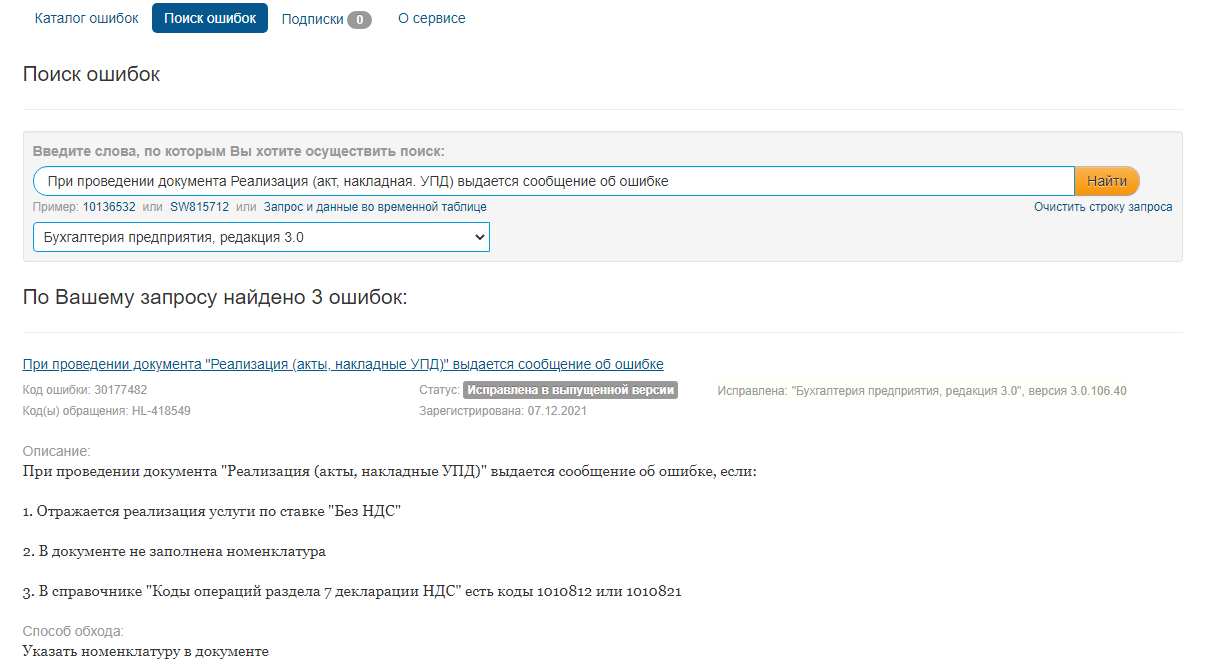
Если ошибка зарегистрирована, сервис поиска отобразит указанную ошибку и версию 1С, в которой она исправлена или планируется к исправлению. Остается дождаться обновления и выполнить его.
Проверьте состояние ПК
Часто ошибки вызваны внешними причинами (отключилось электропитание, «моргнул» свет, не завершились обновления на ПК и т. д.). Что делать в этом случае? БухЭксперт8 рекомендует начать с самых простых действий.
Перезагрузите компьютер
Это первое, что нужно делать в любых непонятных ситуациях. При перезагрузке компьютера очищается память ПК и удаляется «мусор», собравшийся во время работы, — то, из-за чего программа может сбоить и выдавать ошибки.
Всегда начинайте с этого примитивного, но очень полезного действия!
Проверьте обновления ПК
Если они есть, но еще не установлены — запустите процесс обновления. Отсутствие актуальных обновлений системы часто блокирует нормальную работу приложений и 1С в том числе.
Проверьте наличие свободного места на дисках
При отсутствии свободного места на дисках ПК (не менее 500 Мб) 1С не сможет сохранять временные файлы по выполняемым операциям. Это приведет к ошибкам. Контролируйте свободное место на дисках компьютера и своевременно освобождайте дисковое пространство от ненужных и старых файлов.
Выполните действие с ошибкой повторно
После перезагрузки ПК, проверки обновлений и наличия свободного места на компьютере выполните действие с ошибкой повторно: удалите некорректный документ или операцию и введите снова. В 99,99% случаев именно это и помогает.
Подготовка к работе с ошибкой
Если предыдущие действия не помогли, переходите к анализу ошибки типовыми средствами 1С. Для этого выполните следующие операции:
Сделайте копию базы данных
Сделать копию базы необходимо для исключения риска потери данных. При попытке исправить ошибку можно внести в базу данных необратимые изменения. Наличие архивной копии всегда позволит восстановить базу или передать данные программисту, если исправить ошибку самостоятельно не получится.
Очистите кеш 1С
Если программа внезапно стала выдавать ошибку — скорее всего, проблема в кеше. Чистить кеш рекомендуется всегда при появлении ошибок, особенно, если было аварийное отключение питания, подключение собственных доработок кода или выполнение динамического обновления 1С. По статистике на чистку кеша 1С приходится большинство исправленных ошибок программы. Пользуйтесь этим инструментом постоянно!
Проведите тестирование из Конфигуратора
Встроенная в Конфигуратор команда Тестирование и исправление базы проверяет ссылочную и логическую целостность базы данных, проводит ее переиндексацию, пересчет итогов и пытается исправить полученные при тестировании ошибки. Если чистка кеша 1С в предыдущем пункте не помогла, тестирование базы — это следующее действие, которое обязательно нужно выполнить.
Проверьте базу специальной утилитой CHDBFL
Платформы 1С содержат специальную утилиту CHDBFL.exe, которая предназначена для проверки физической целостности внутренних таблиц в программе. Ошибки во внутренних таблицах относятся к разряду самых тяжелых: нарушение физической целостности может блокировать сам вход в программу! Эта утилита не только найдет, но и в автоматическом режиме запустит действия по исправлению выявленных нарушений.
Детализация ошибки
Если предыдущие действия не исправили ситуацию и проблема осталась, переходите на следующий уровень работы с ошибкой — детализации проблемы. Это автоматически предполагает наличие ошибок в самом коде программы. Порядок действий такой:
Обновитесь на актуальный релиз
Бывают ошибки, допущенные разработчиками при подготовке обновлений 1С. Они быстро обнаруживаются и исправляются в последующих релизах программы. Если у вас появилась ошибка в программе, проверьте актуальность версии 1С и при необходимости выполните обновление.
Обновите платформу 1С
Если обновление на актуальный релиз не помогло, можно попробовать запустить 1С с другой платформы. Запуск с новой платформы автоматически чистит кеши 1С, подключает доработанный и исправленный функционал. Это успешно решает проблему в определенных случаях.
Установите в 1С возможность получать патчи
Установка патчей (исправлений) позволит быстро исправлять зарегистрированные ошибки разработчиков, не дожидаясь выхода обновлений 1С. Это уменьшит число появления ошибок при работе с программой.
Проверьте наличие в расширениях неактуальных патчей
При автоматической загрузке патчей проверьте, что среди них нет устаревших. Неактуальные патчи должны автоматически удаляться из подключенных расширений базы при обновлении 1С. Если какие-то старые патчи не удаляются — это приводит к ошибкам. Удалите найденные неактуальные патчи в вашей базе и перезапустите 1С.
Типовые ошибки и их исправление
Чтобы качественно вести бухгалтерский и налоговый учет, бухгалтеру приходится разбираться не только с дебетом и кредитом, но и с самой программой. Значит, ему нужны хотя бы минимальные знания администрирования 1С, представление о типовых ошибках программы и методах их исправления. Далеко не каждая организация может позволить себе иметь собственного программиста.
Для помощи «бухгалтерам-без-программистов» команда БухЭксперт8 подготовила специальный сборник ПУТЕВОДИТЕЛЬ по ошибкам и их исправлению в 1С. Сохраните эту страничку в социальных сетях или в закладках как шпаргалку. Пользуйтесь ею онлайн всегда, когда необходимо исправить ошибки 1С 8.3.
Для дополнительной профессиональной помощи
в работе с 1С:Бухгалтерия 3.0 БухЭксперт8 рекомендует
специальный авторский курс Ольги Шерст
Бухгалтерский и налоговый учет в 1С:Бухгалтерия 8 ред.3 от А до Я,
ОСНО или УСН на ваш выбор
См. также:
- Бухгалтер без Админа при работе с 1С:Бухгалтерия
- Как установить патчи (исправления) в 1С
- Исправление технических ошибок при работе с 1С:Бухгалтерия
- Утилита chdbfl.exe для 8.3
- Тестирование и исправление базы 1С
- 1С оптимизация: что делать, если программа тормозит
- Как сделать копию базы 1С
- Очистка кэш
Если Вы еще не подписаны:
Активировать демо-доступ бесплатно →
или
Оформить подписку на Рубрикатор →
После оформления подписки вам станут доступны все материалы по 1С:Бухгалтерия, записи поддерживающих эфиров и вы сможете задавать любые вопросы по 1С.
Подписывайтесь на наши YouTube и Telegram чтобы не пропустить
важные изменения 1С и законодательства
Помогла статья?
Получите еще секретный бонус и полный доступ к справочной системе БухЭксперт8 на 14 дней бесплатно
Ой! Данный функционал ещё в разработке
Текст ошибки может звучать по-разному, например:
- Поле объекта не обнаружено (ХХХХХХ);
- Значение не является значением объектного типа (ХХХХХХ);
- Метод объекта не обнаружен (ХХХХХХ);
- Во время сохранения файла возникла ошибка.
Такие ошибки чаще всего возникают при некорректной работе базы 1С.
Для решения может помочь одно из следующих действий:
- Очистите кэш платформы 1С.
- Проверьте права пользователя в 1С.
- Проверьте, включено ли использование внешнего модуля. Если да, создайте резервную копию информационной базы, после чего отключите внешний модуль.
Внешний модуль в управляемых конфигурациях (БП 3.0, ЗУП 3.1 и др.) находится в прочих настройках обмена. Если отметка проставлена — снимите её, после чего перезапустите 1С.
Внешний модуль в неуправляемых конфигурациях (БП 2.0, ЗУП 2.5, УПП 1.3 и др.) находится по пути Отчеты → Регламентированные отчеты → Настройки → Для настройки параметров документооборота нажмите здесь (внизу). Отметьте пункт Использовать встроенный модуль документооборота, после чего перезапустите 1С.
- Сделайте диагностику 1С-отчетности, отправьте отчет по диагностике и сообщите номер обращения специалисту технической поддержки 1С-Отчетность.
- Запустите Конфигуратор 1С. Выберите пункт Отладка → Начать отладку.
- Удостоверьтесь, что конфигурация находится на полной поддержке 1С, т.е. в нее не были внесены изменения и она соответствует конфигурации поставщика.
Запустите Конфигуратор 1С. Если конфигурация закрыта, то необходимо ее открыть: Конфигурация → Открыть конфигурацию. Слева в меню напротив названия конфигурации должен быть значок замка – объект поставщика не редактируется.
- Попробуйте запустить 1С в тонком клиенте, для этого после нажатия на ярлык 1С выберите базу, затем нажмите Изменить → Далее → Основной режим запуска: выберите пункт Тонкий клиент → Готово. Запустите 1С.
- Измените переменные среды. Рекомендуем обратиться к системному администратору для выполнения данных действий.
- Проверьте кодировку в операционной системе Windows по инструкции смена кодировки. Рекомендуем обратиться к системному администратору для выполнения данных действий.
В случае системного языкового пакета, отличного от русского, программа 1С не может работать с внешней компонентой для отображения сертификатов. Для решения этой ситуации можно изменить параметры в системном реестре. Рекомендуем обратиться к системному администратору для выполнения данных действий.
Номер статьи: 129674145
Обновлено: 01.08.2023 11:36+0000