У меня эта ошибка выскакивала раз 6 за 2 недели. Успешно сбрасывалась елмом.
Подробно на ютупе пиндосы объясняли как разбирать и куда смотреть, необходимо набрать в запросе номер ошибки и приус.
на драйве решение описано в следующих записях:
www.drive2.ru/b/542263467852170381/
www.drive2.ru/l/457482325257647600/
www.drive2.ru/l/475511842…age=0#a585909681428377295
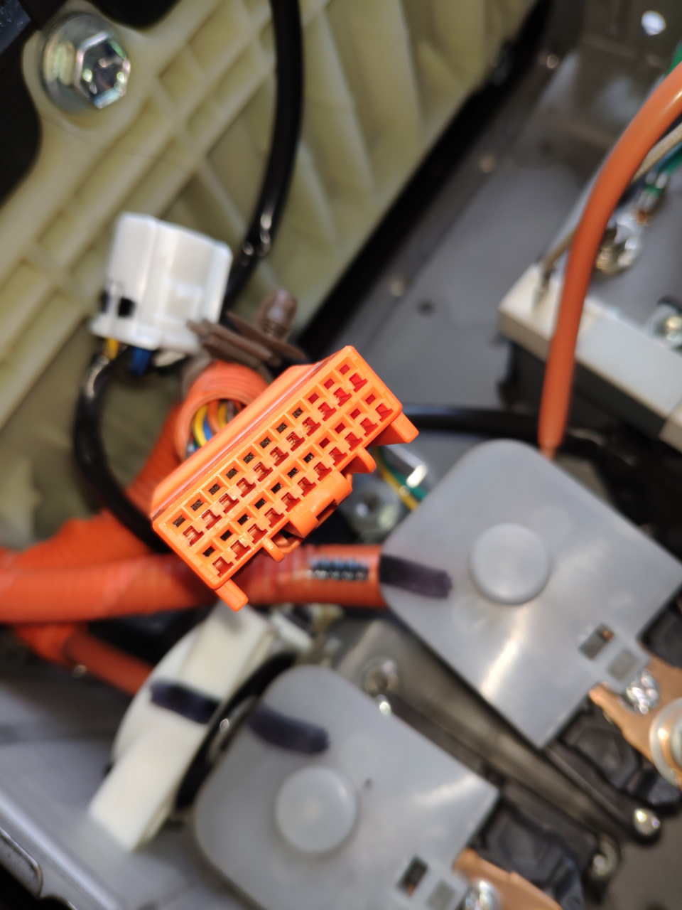
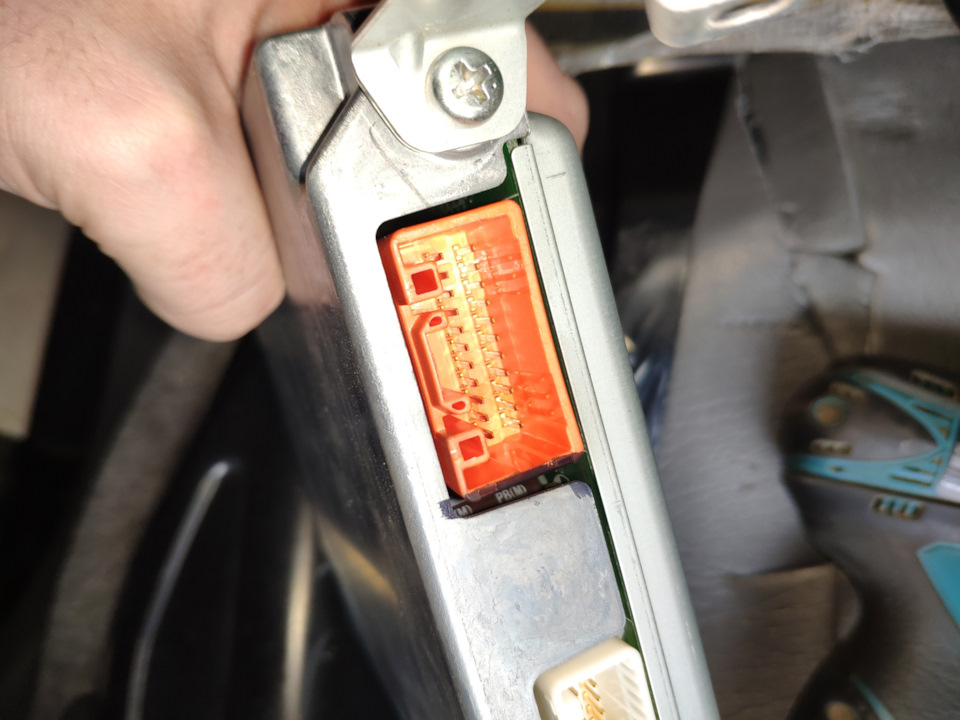
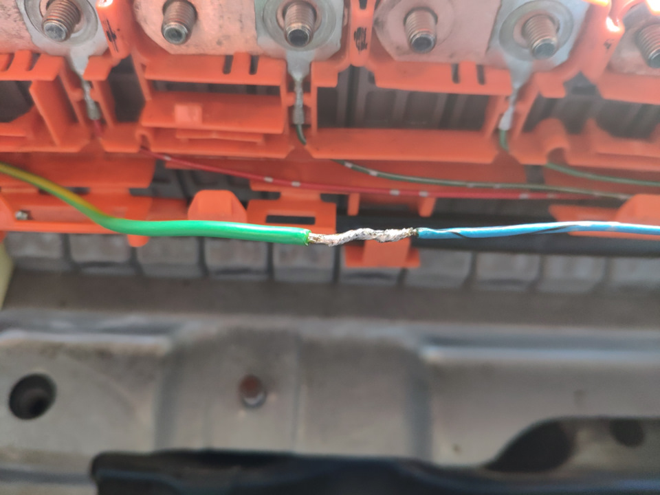
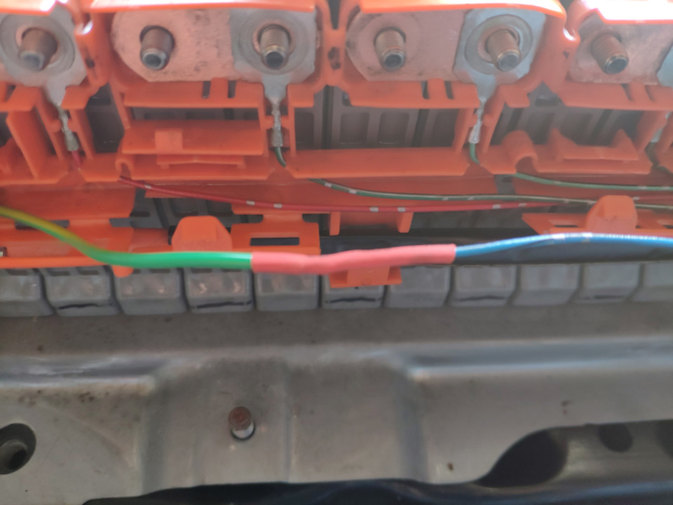
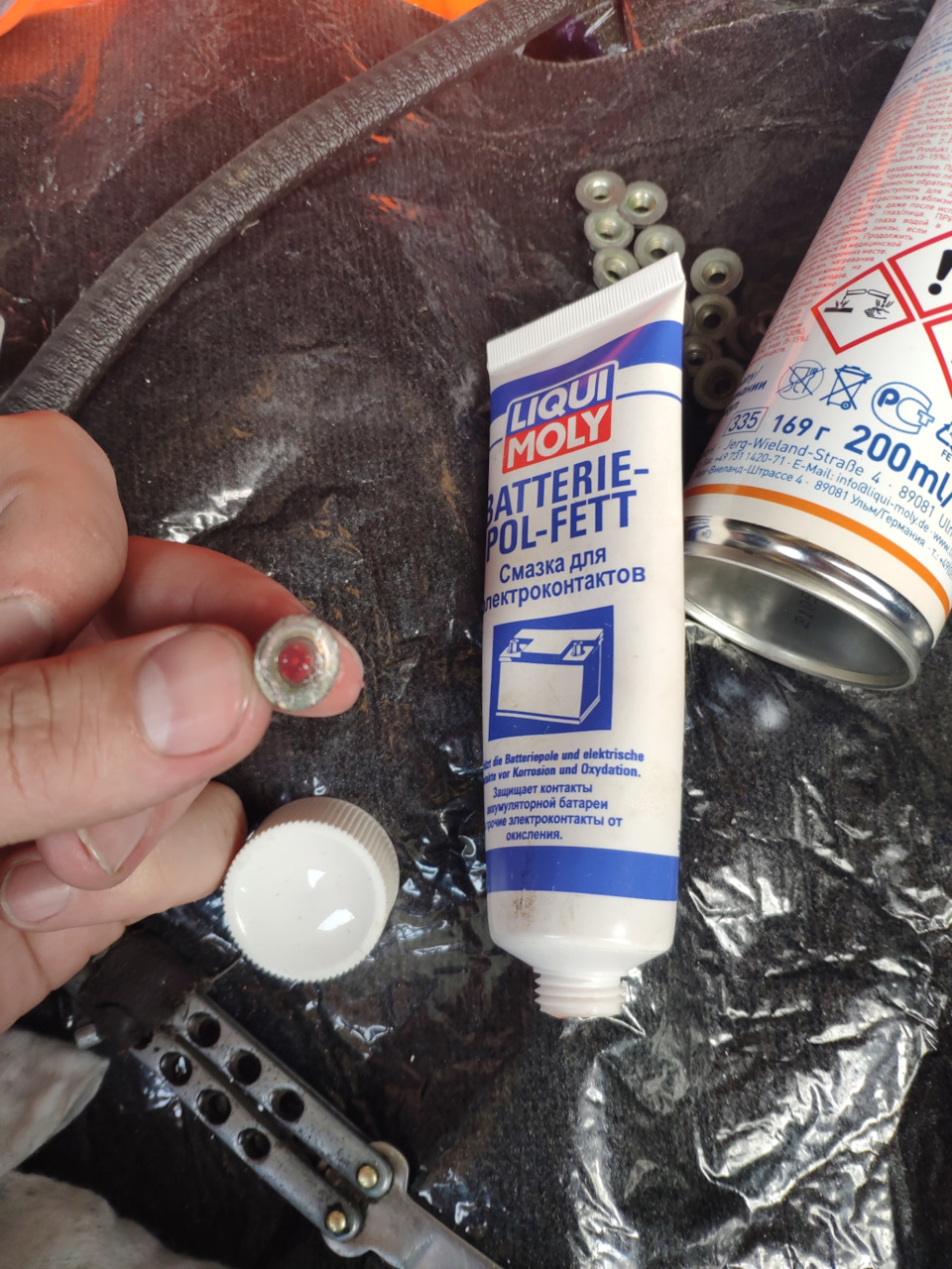
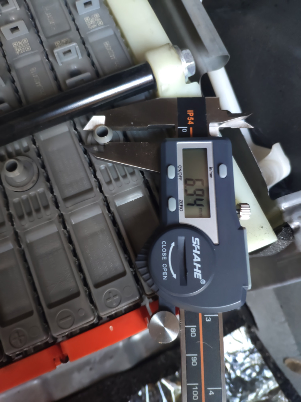
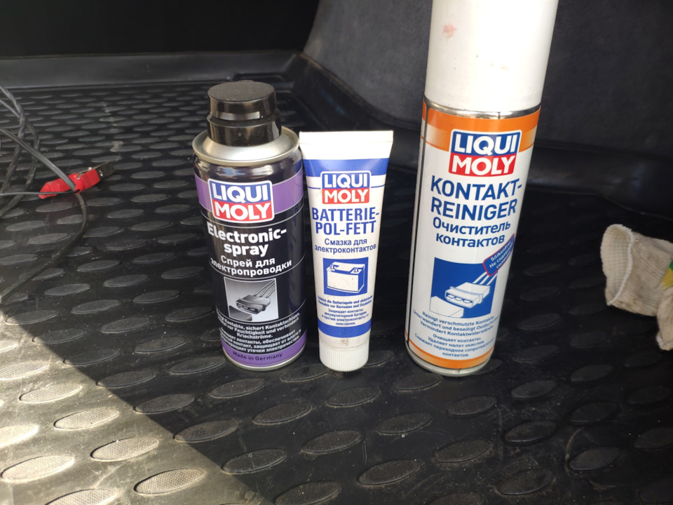
Разъем я обработал составом для электропроводки.
Пластины чистил дремелем. Затем обработал составом для электропроводки.
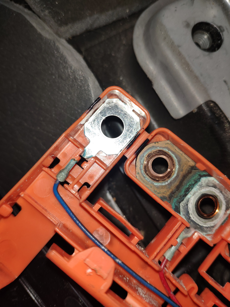
Гайки обрабатывал очистителем электроконтактов + зубной щеткой чистил.
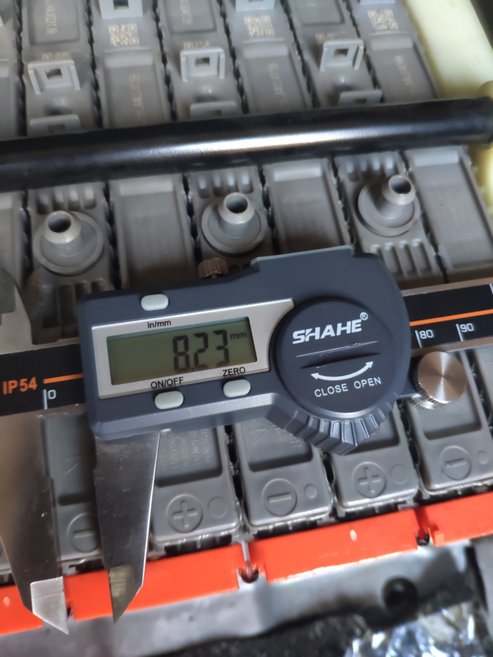
Затем, после обратного монтажа пластин и гаек — смазывал зубной щеткой сверху смазкой для электроконтактов.
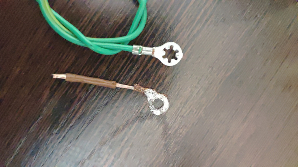
Оборванную клемму заменил тем что было под рукой.
Но я бы советовал до разбора ВВБ искать подобную родной тонкую оцинкованную клемму с большой площадью.
И я бы советовал сразу припастись силиконовыми шлангами вместо роднойрезиновой перемычки тк родная пахнет тем самым запахом, что мы замечаем, принюхиваясь возле вентиляционного окна.
Я же просто замочил в растворе с белезной, высушил и обработал силиконовой смазкой. Врядли это помогжет избавиться от запаха).
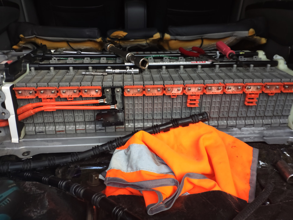
p.s: раньше я топил за то, что лезть в ввб и наводить марафет на контактах пластин это из разряда когда коту делать нечего. но сейчас я изменил свою точку зрения. лезть туда нужно, как минимум потому что вы успеете обслужить разъем до того как пины начнуть окисляться и коррозия убъет оцинкованные клеммы на ввб. главное запастись всем необходимым из спецжидкостей, тк с завода пластины покрыты лаком и без обработки это все окислиться очень быстро.
Цена вопроса: 1 400 ₽
Пробег: 203 000 км
-

- Joined:
- Oct 2, 2014
- 106
- 35
- 0
- Location:
- Lagos
- Vehicle:
- 2015 Prius Plug-in
- Model:
- Plug-in Base
Okay Guys, i am having this issue with my 2010 Prius 97k miles. Took it to a friend who owns a car lot so that it could be sold (using a PIP). My friend’s employee on a daily basis moves the car from the night parking location to the sales spot, a distance of less than 15 meters. On this day, he returned the car to the night parking location and it won’t come ready the next morning.
The car flashes Ready for <5 seconds and shuts down. Engine does not start and Transmission cannot be engaged successfully.
I ran a scan using Techstream and pulled some codes. The following codes below have been my primary focus
P0517
P0A80
P0AFC -123
P0B42 -123
U0100 — 211These are the things that i have done so far.
I have changed the Battery Smart Unit and the codes remain the same. Following the diagnostic tree for P0AFC-123, checked the resistance between BSU C1-4 (IGCT) to IGCT No.2 (2) and it was within limits.Checked the IGCT Fuse, IGCT No.2 Fuse and IGCT Relay and all three (3) components tested within limits.
Now i am kinda lost and need the senior fellows here to assist to bring back my dear dear Prius.
Attached Files:
-
Hook a booster pack or jumper cables to the jump point under the hood. The 12v battery is very low. 10.58v. Clear the codes and try to start it again.
-
- Joined:
- Oct 2, 2014
- 106
- 35
- 0
- Location:
- Lagos
- Vehicle:
- 2015 Prius Plug-in
- Model:
- Plug-in Base
Thank you Sir for your prompt response…will do that and revert asa possible.
-
The main reason I call this out, if it drove with no issue 24 hours prior, there can’t possibly have been something serious “just happen” without some kind of warning. The most important thing to remember about the Prius, is don’t “overthink” the issue.
-
- Joined:
- Oct 2, 2014
- 106
- 35
- 0
- Location:
- Lagos
- Vehicle:
- 2015 Prius Plug-in
- Model:
- Plug-in Base
Okay, i went in there and tried to get the car ready with a new auxiliary battery and it was the same thing — won’t start. Pulled some codes from Techstream again and this time i got another hybrid code in addition to the previous ones listed in the initial post.
P0B3D-123 Hybrid Battery Voltage Sensor «A» Circuit Low
Also noticed that Battery Block 1 had taken a hit @ 9V compared to other blocks which are between 14.96V and 15.01 V indicating that the battery is getting negatively impacted by the times that i had tried to get the car ready. Nothing has changed in the car except for the replacement Battery Smart Unit which was introduced. At this point, i don’t know if the bad Block 1 has been a lingering issue. Reviewing the techstream codes from the initial post (pdf), i observed that Block 1 had started to differ from the rest of the blocks @13.75V compared the rest of the blocks which were between 15.4V to 17.5V, could this have triggered those sets of initial codes?. Nevertheless, i have pulled out the battery pack for a charge. For now the plan is just to charge the pack, review the codes some more and try to get the car started. If i can get the car started, then i can take a further look at the battery pack, i hope that i haven’t ultimately damaged it.
Will appreciate any further insights and discussions on progressing and learning more about any possible causes so as to close out on this.
Attached Files:
-

11.PNG
- File size:
- 225.1 KB
- Views:
- 0
-
- Joined:
- Oct 2, 2014
- 106
- 35
- 0
- Location:
- Lagos
- Vehicle:
- 2015 Prius Plug-in
- Model:
- Plug-in Base
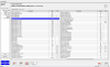
Had some time for some more troubleshooting today, this time i followed the diagnostic tree for U0100 Lost communication with PCM / ECM «A» and still unable to rectify the issue. Car comes ready but the gasoline engine will not turn. One of the diagnostics tree pointed to running a CAN BUS CHECK in Techstream which i did ….simply put, ECU’s in red (attached) not communicating on the CAN BUS line, I don’t know if this is normal or due to a malfunction of the one or more ECU’s connected to the CAN BUS. I have checked for short and open on the CAN BUS line by measuring the resistance between CANH and CANL and battery (pin 16 on DLC 3) with battery terminals connected and negative terminal removed, and the measurements were within the specifications.
I have also changed the HV battery along with the Battery ECU, got 2 days subscription to Toyota TIS and got some useful materials. Since U0100 was pointing to Communication loss between ECM / PCM — i went ahead to check the CAN BUS wire for disconnection by measuring the resistance between CANN and CANP and i measured 123 ohms which is within the specified condition.
The following hybrid codes still exist as permanent even after the change
U0100 — 211
P0AFC — 123
P0B42
P0A80I need help with this. Clearly looking at these options now
1. Open in a harness not yet discovered
2. ECM malfunction
3. Power Management Control ECU malfunction
4. Transmission malfunctionAttached Files:
-
- Joined:
- Oct 2, 2014
- 106
- 35
- 0
- Location:
- Lagos
- Vehicle:
- 2015 Prius Plug-in
- Model:
- Plug-in Base
Okay, its been a while since this post, i have largely been out of town and the car was parked far away from my house. Anyways, i had to tow the car to my house for convenience of troubleshooting it. I also thought about it, the car was absolutely fine before i took it to the car sales place. I remembered that one of the times i visited the cars sales shop, the personnel were using one 12v battery to move multiple cars from their overnight parking lot to the showroom. It dawned on me that the issue could easily have been a wrong jump start i.e jump staring the Prius wrongly. Unlike the Prius Gen 2, the fusible link in the Prius Gen 3 is in the trunk area by the battery and it was intact (visibly and a resistance test). Then i rechecked the CANBUS read out from Techstream (attached in previous post) and realized that the ECM was not communicating in the CANBUS. The CANBUS has two terminating 120Ohm resistors, one in the ECM and the other in the Combination meter…..Anyways, i changed the ECM and the car came READY.
The only thing i noticed now is that the touchscreen display does not respond to touch, so i have to change the audio mode from the buttons on the steering wheel. Besides that the car has returned to normal.
-
- Joined:
- May 29, 2018
- 5,273
- 2,922
- 0
- Location:
- Florida
- Vehicle:
- 2010 Prius
- Model:
- Two
Have you checked the 12v battery??? It may be weak..
-
- Joined:
- Oct 2, 2014
- 106
- 35
- 0
- Location:
- Lagos
- Vehicle:
- 2015 Prius Plug-in
- Model:
- Plug-in Base
Thanks for the response. I changed the 12V battery outrightly because the previous one had run down. still the touchscreen no response issue.

DTC
P0AFC-129 Hybrid Battery Pack Sensor Module
for Preparation Click here
DESCRIPTION
The battery smart unit (battery energy control module) sends HV battery voltage information to the power management control ECU via serial communication.
| DTC No. | INF Code | DTC Detection Condition | Trouble Area |
| P0AFC | 129 | Battery voltage sensor malfunction (HV battery voltage sensor malfunction) When not boosting the difference between «Power Resource VB» and «VL-Voltage before Boosting» is large, and also «Power Resource VB» and «VH-Voltage after Boosting» is large. (1 trip detection logic) |
Battery smart unit |
| DTC No. | Data List |
| P0AFC-129 |
|
The following items can be helpful when performing repairs:
Data List
- Ready Signal
MONITOR DESCRIPTION
The power management control ECU calculates the differences between the received HV battery voltage, boost converter voltage, and inverter voltage. If the differences exceed prescribed values, the power management control ECU determines that there is a malfunction in the battery smart unit circuit. When the power management control ECU detects this malfunction, it will illuminate the MIL and set a DTC.
MONITOR STRATEGY
| Related DTCs | P0AFC (INF 129): Voltage (VB) sensor deviation |
| Required sensors / components | Battery smart unit |
| Frequency of operation | Continuous |
| Duration | TMC’s intellectual property |
| MIL operation | 1 driving cycle |
| Sequence of operation | None |
TYPICAL ENABLING CONDITIONS
| The monitor will run whenever the following DTCs are not present | TMC’s intellectual property |
| Other conditions belong to TMC’s intellectual property | — |
TYPICAL MALFUNCTION THRESHOLDS
| TMC’s intellectual property | — |
COMPONENT OPERATING RANGE
| Power management control ECU | DTC P0AFC (INF 129): is not detected |
CONFIRMATION DRIVING PATTERN
- Connect the Techstream to the DLC3.
- Turn the ignition switch to ON (IG) and turn the Techstream on.
- Clear the DTCs (even if no DTCs are stored, perform the clear DTC procedure).
- Turn the ignition switch off and wait for 30 seconds or more.
- Turn the ignition switch to ON (IG) and turn the Techstream on.
- Turn the ignition switch to ON (READY).
- With the shift lever in D, depress both the accelerator pedal and brake pedal at the same time to raise the SOC to a sufficient level.
- Move the shift lever to P, check that the engine is stopped.
- Set the A/C for maximum cooling.
- Leave the vehicle for a few minutes.
- HINT:
- During step 9, make sure that the engine is stopped. If the engine starts, restart from step 6.
- Enter the following menus: Powertrain / Hybrid Control / Trouble Codes.
- Read the current DTCs.
- HINT:
- If a current DTC is output, the system is malfunctioning.
- If a current DTC is not output and want to confirm permanent DTC, perform the following procedure.
- Check that permanent DTCs are cleared. If no permanent DTC is output, the system is normal.
- If the permanent DTCs are not cleared, perform the universal trip, and then check for permanent DTCs again.
INSPECTION PROCEDURE
- NOTICE:
- Performing the check procedures for a long time with the shift lever in N may cause DTC P3000-388 to be set.
- HINT:
- After performing troubleshooting, if it is necessary to replace the battery smart unit, voltages need to be confirmed after installing the new battery smart unit. Confirm that «Power Resource VB», «VL-Voltage before Boosting», and «VH-Voltage after Boosting» in the Data List are 155 V or more with the ignition switch to ON (READY), shift lever in P, and the engine stopped. When the system is normal, the «Power Resource VB», «VL-Voltage before Boosting», and «VH-Voltage after Boosting» values should be almost equal (voltage boosting will not occur when the shift lever is in N). If the difference between each voltage exceeds the values specified below, there must be a malfunction in the battery smart unit or the inverter with converter assembly.
- After performing troubleshooting, if it is necessary to replace the battery smart unit, voltages need to be confirmed after installing the new battery smart unit. Confirm that battery voltages (Power Resource VB), pre-boost voltage (VL), and post-boost voltage (VH) in the Data List are 220V or more with the ignition switch to ON (READY), shift lever in P, and the engine stopped. When the system is normal, the Power Resource VB, VL, and VH values should be almost equal (voltage boosting will not occur when the shift lever is in neutral). If the difference between each voltage exceeds the values specified below, there must be a malfunction in the battery smart unit or the inverter with converter assembly.
Inspection voltage Maximum voltage difference Difference between «Power Resource VB» and «VL-Voltage before Boosting» 35 V Difference between «Power Resource VB» and «VH-Voltage after Boosting» 60 V Difference between «VL-Voltage before Boosting» and «VH-Voltage after Boosting» 80 V - After the repair, if «VL-Voltage before Boosting» and «Power Resource VB» are approximately the same when the ignition switch is turned to ON (READY) with the shift lever in P and the accelerator pedal not depressed, the condition is judged as normal.
1.CHECK DTC OUTPUT (HYBRID CONTROL)
-
Connect the Techstream to the DLC3.
-
Turn the ignition switch to ON (IG).
-
Enter the following menus: Powertrain / Hybrid Control / Trouble Codes.
-
Check if DTCs are output.
- Result:
-
Result Proceed to Only P0AFC-129 is output or P0AFC-129 and DTCs other than the ones in the table below are also output. A DTCs shown in Table 1 are output simultaneously. B DTCs shown in Table 2 are output simultaneously. C
Table 1
DTC No. Relevant Diagnosis P0A1A-151, 155, 156, 658, 659 Generator Control Module P0A1B-164, 193, 512, 661, 786 Drive Motor «A» Control Module P0A1D-148 Hybrid Powertrain Control Module P0A78-266, 267 Drive Motor «A» Inverter Performance P0A94-589, 590 DC/DC Converter Performance P2511-149 ECM/PCM Power Relay Sensor Circuit Intermittent P3004-132 High Voltage Power Resource P324E-788 MG-ECU Power Relay Intermittent Circuit U0110 (all INF codes)*1 Lost Communication with Drive Motor Control Module «A» Table 2
DTC No. Relevant Diagnosis P0AFC-123 Hybrid Battery Pack Sensor Module P0B3D-123 Hybrid Battery Voltage Sensor «A» Circuit Low P0B42-123 Hybrid Battery Voltage Sensor «B» Circuit Low P0B47-123 Hybrid Battery Voltage Sensor «C» Circuit Low P0B4C-123 Hybrid Battery Voltage Sensor «D» Circuit Low P0B51-123 Hybrid Battery Voltage Sensor «E» Circuit Low P0B56-123 Hybrid Battery Voltage Sensor «F» Circuit Low P0B5B-123 Hybrid Battery Voltage Sensor «G» Circuit Low P0B60-123 Hybrid Battery Voltage Sensor «H» Circuit Low P0B65-123 Hybrid Battery Voltage Sensor «I» Circuit Low P0B6A-123 Hybrid Battery Voltage Sensor «J» Circuit Low P0B6F-123 Hybrid Battery Voltage Sensor «K» Circuit Low P308A-123 Hybrid Battery Voltage Sensor All Circuits Low - HINT:
- *1: If any INF codes are output for this DTC, refer to the corresponding diagnostic procedure.
- P0AFC-129 may be output due to a malfunction which causes the DTCs in the table above to be output. In this case, first troubleshoot the output DTCs in the table above. Then, perform a reproduction test to check that no DTCs are output.
-
Turn the ignition switch off.
| A | |
OBD-II Trouble Code Technical Description
Article by
Stephen Darby
ASE Certified Technician
Hybrid Battery Pack Sensor Module
What does that mean?
This is a generic diagnostic trouble code (DTC) and applies to many OBD-II vehicles (1996-newer). That may include but is not limited to vehicles from Toyota, Honda, Ford, Subaru, etc. Although generic, the exact repair steps may vary depending on year, make, model and powertrain configuration.
If your OBD II equipped, hybrid vehicle (HV) has stored a code P0AFC, it means that the powertrain control module (PCM) has detected a malfunction in the hybrid battery pack sensor module. The hybrid battery pack sensor module is more commonly referred to as the hybrid vehicle battery control module (HVBCM). This code should be exhibited only in hybrid vehicles.
The primary responsibility of the HVBCM (which interacts with the PCM and other controllers) is to monitor and control the the high-voltage battery pack. Twenty-eight (nickel metal-hydride) batteries, configured of eight separate 1.2-volt cells — arranged in series, make up the HV battery pack. The high voltage hybrid battery packs are wired in series with busbar connectors and sections of high voltage copper cable.
Battery temperature, individual cell resistance, battery charge levels, and overall battery pack condition are included among the functions monitored and calculated by the HVBMS.
The HVBMS receives input data from each individual cell in order to monitor individual battery/cell temperature and resistance levels in the battery pack. This information is used to regulate battery charge rates and operate battery cooling fans (among other things). Each individual cell (or battery, depending upon the type of system) is outfitted with an integrated ammeter/temperature sensor.
If the HVBMS provides the PCM with an input signal that indicates a HVBCM (hybrid battery pack sensor module) malfunction has occurred, a code P0AFC will be stored and a malfunction indicator lamp may be illuminated. Most vehicle applications will require multiple failure cycles prior to MIL illumination.
A typical hybrid battery pack:

What is the severity of this DTC?
Hybrid battery pack sensor module/HVBCM failure (and a stored code P0AFC) could result in deactivation of the electric propulsion system. The P0AFC should be addressed with urgency.
What are some of the symptoms of the code?
Symptoms of a P0AFC trouble code may include:
- Diminished vehicle performance
- Decreased fuel efficiency
- Other HV battery related codes
- Electric propulsion system deactivation
What are some of the common causes of the code?
Causes for this code may include:
- Defective HV battery, cell, or battery pack
- Loose, broken, or corroded busbar connectors or cables
- HVBMS sensor failure
- Controller failure of programming error
What are some P0AFC troubleshooting steps?
The high-voltage battery system should only be serviced by qualified personnel.
Access to a diagnostic scanner, a digital volt/ohmmeter (DVOM), and a source of HV battery system diagnostic information will be necessary before attempting to diagnose a code P0AFC.
I like to begin my diagnosis with a visual inspection of the HV battery pack and all controller area network (CAN) harnesses. I would focus on signs of corrosion, damage, or other obviously open circuits. Remove corrosion and repair (or replace) defective circuitry as required. Before performing any battery load testing, make sure that there are no corrosion issues present on the battery pack, that all connections are secure, and that the battery pack is fully charged.
Proceed by connecting the scanner to the vehicle diagnostic connector and retrieving all stored codes and pertinent freeze frame data. Record this information before clearing the codes and test driving the vehicle until the PCM either enters readiness mode or the code is reset.
If the PCM enters readiness mode (no codes stored) at this point; the code is intermittent and may be much more difficult to diagnose.
You may suspect a defective HVBCM/PCM or a controller programming error if all controller power (input) and ground circuits are intact and there is no sensor power (output) supply voltage from the HVBCM/PCM. Controller replacement will require reprogramming.
If there is no HVBCM supply voltage present, test all related controller power supply fuses and relays. Replace defective components as required.
Any controller that shows signs of water, heat, or collision damage should be considered defective.
- While a stored code P0AFC may not automatically deactivate the HV battery charging system but the conditions which caused the code to be stored may disable it
Related DTC Discussions
- There are currently no related topics in our forums. Post a new forum topic now.
Need more help with a P0AFC code?
If you still need help regarding the P0AFC trouble code, please post
your question in our FREE car repair forums.
NOTE: This information is presented for information purposes only.
It is not intended as repair advice and we are not responsible for any actions
you take on any vehicle. All information on this site is copyright protected.
Автор:
Julia Ray
Дата создания:
6 Август 2021
Дата обновления:
13 Сентябрь 2023

Содержание
- Возможные причины
- Возможные симптомы
- P0afc Описание
Возможные причины
Возможные симптомы