8
The tables below show the possible malfunctions and the corresponding causes as well as the
steps to be taken.
For a more detailed way of troubleshooting, please refer to the Call Scripts on page 60.
Malfunction
Control panel does not
illuminate.
The control panel is on, but
there is no activity after closing
the lid.
Insufficient end vacuum.
Vacuum process is slow.
Vacuum bag is not sealed
correctly.
Activity
• Connect the machine to the
power supply.
• Check the circuit breaker on
the back of the machine.
• Check or adjust the switch of
the lid.
• Check the vacuum settings
of the program and adjust
them.
• Make sure that the
extraction opening is not
covered.
• Check the oil level in the
pump.
• Check/replace the oil
exhaust filter.
• Check/replace the lid
gasket.
• Make sure that the
extraction opening is not
covered.
• Check the oil level in the
pump.
• Check/replace the oil
exhaust filter.
• Check the seal settings
of the program and adjust
them.
• Check/replace the Teflon
tape and the sealing wires.
• Check/replace the silicone
rubber of the silicone
holders.
More information
Electrical Installation on page
17.
Contact your supplier.
Changing the Program Settings
on page 23.
Vacuum Pump on page 16.
Replacing the Oil Exhaust Filter
on page 31.
Replacing the Lid Gasket on
page 35.
Vacuum Pump on page 16.
Replacing the Oil Exhaust Filter
on page 31.
Changing the Program Settings
on page 23.
Replacing the Sealing Wire on
page 33.
Replacing the Silicone Rubber
of the Silicone Holders on page
35.
Troubleshooting and Error Codes
37
-
Из воздушного фильтра выходит Белый дым, что это? И отсек с воздушным фильтром с низу наполняется маслом. Аппарат работает хорошо. Подскажите пожалуйста куда смотреть, в чем может быть проблема? Пишу коротко так как с телефона. Заранее спасибо.
Последнее редактирование: 26 янв 2017
-
Белый дым — это распылённая масло-водяная смесь. Поставить какую-нибудь плоскость под неё и будет видно. Всё это явный признак что фильтр под замену или промывку. Возможно требуется полная замена масла в вакуумнике. Стало много воды.
-
Предусмотренная сервисная система сушки насоса способствует удалению скопившейся влаги и продлению его службы.
-
Ребят, а масло почему гонит к воздушном фильтру?
-
там клапан должен быть не забит?
-
Его не гонит , просто на лицевой панели слева внизу есть черная кнопка , запускающая процедуру очистки масла в помпе отводы.
Работает она 15 минут , делаться должна 1 раз в неделю при 8-часовом графике работы.
Фильтр из которого идут масляно-водяные пары — должен независимо ни от чего меняться каждые 400 часов работы ( кто то его в ацетоне моет и сушит ). Как показывает практика ,80 % пользователей — фильтра вообще не меняют — дорого! Хотя в соотношении с ценой нового аппарата — 10 — 20 % на ЗИП , не так уж и много. -
При работе на нем, масло поступает через тот болт который на видео в отсек с фильтром, это нормально?
-
нет не должно так быть , это воздушная камера
-
Может есть врыв схема на этот насос чтоб посмотреть откуда масло? Просто аппарат работает, вакуумирует и запаивает отлично. А вот булькание масла в этой камере напрягает, раньше такого не было.
-
Скорее всего протечка в самом месте сочленения , первый раз встречаю именно такую поломку.
Взрыв схему на вакуумный насос не встречал ни разу в жизни.
Попробуйте запросить у поставщиков запчастей и оборудования , СПО МАРКЕТ — например. -
Вложения:
-
Мне кажется , его это не спасет — ему помпа в разрезе нужна.
-
думаю да же дилеру не даст завод такую схему
-
Согласен с Вами , особенно сейчас , когда все у всех все копируют
))")
))")
Поделиться этой страницей
-
Contents
-
Table of Contents
-
Troubleshooting
-
Bookmarks
Quick Links
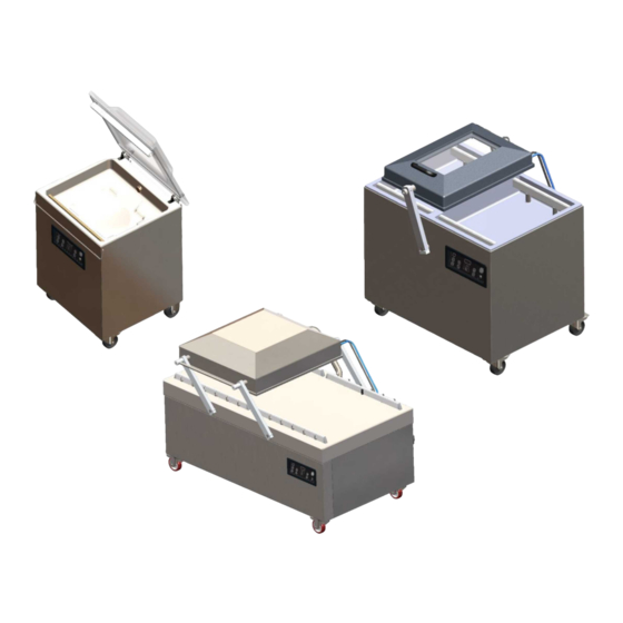
Vacuum Packaging Machine
Marlin, Falcon, Polar
User Manual
Art No. 0895011
Original Instructions for Use
©
Henkelman 2017
Related Manuals for Henkelman Marlin
Summary of Contents for Henkelman Marlin
-
Page 1
Vacuum Packaging Machine Marlin, Falcon, Polar User Manual Art No. 0895011 Original Instructions for Use © Henkelman 2017… -
Page 2
Henkelman BV accepts no liability for damage and/or problems arising from the use of spare parts not supplied by Henkelman BV. This user manual has been compiled with all possible care. Henkelman BV assumes no responsibility for any errors in this manual and/or the consequences of an erroneous interpretation of the instructions. -
Page 3: Table Of Contents
Contents List of Figures……………………..6 1 Preamble……………………….7 2 Safety………………………..8 2.1 List of the Symbols Used in this Manual…………….8 2.2 Pictograms on the Machine………………..8 2.3 General Warnings……………………9 2.4 Warnings During Use………………….10 2.5 Warnings for Operating Personnel………………10 3 Introduction……………………..12 4 Description of the Machine…………………..13 4.1 Overview of the Main Components………………13…
-
Page 4
6.7.1.4 Gas+ (optional)………………… 35 6.7.1.5 Liquid Control (optional)………………35 6.7.1.6 Liquid Control+ (optional)………………35 6.7.1.7 Red Meat (optional)………………..36 6.7.1.8 Multi-Cycle Vacuum (optional)…………….36 6.7.1.9 Seal……………………36 6.7.1.10 Soft-Air (optional for the Falcon)……………. 37 6.7.1.11 External Vacuum (optional)…………….37 6.7.1.12 Sleeper Option………………..38 6.7.2 Advanced Control System (ACS)…………….. 38 6.7.2.1 Programming the ACS Control Using the PC………… -
Page 5
10 Disposal………………………..62 11 Appendices……………………..63 11.1 Technical Data……………………63 11.1.1 Technical Data Marlin………………..63 11.1.2 Technical Data Falcon………………..64 11.1.3 Technical Data Polar………………..66 11.2 Example Programs………………….70 11.3 Logbook……………………..72 11.4 EC Declaration of Conformity……………….. 74 11.5 Replacing a Printer Roll………………… 75 11.6 Aligning the Printer………………….76… -
Page 6: List Of Figures
List of Figures Figure 1: Overview of the Main Components…………….. 13 Figure 2: Overview of the Sealing System (Including Sealing Cylinder)………19 Figure 3: Overview of the Sealing System (Including Seal Bag)………… 19 Figure 4: Overview of the Pump………………… 20 Figure 5: Overview of the Electrical Installation…………….21 Figure 6: Direction of Rotation of the Vacuum Pump…………..
-
Page 7: Preamble
Preamble This is the manual for your Henkelman vacuum packaging machine. This manual is intended for anyone who works with or services the machine. This manual contains information and instructions for installation, operation and maintenance of the machine. We recommend that you carefully read this manual before use and follow the procedures and instructions strictly.
-
Page 8: Safety
Safety Your vacuum packaging machine has been carefully designed and expertly built to be operated safely. This is corroborated by the EC Declaration of Conformity. However, there are always dangers and safety risks that cannot be eliminated. These dangers and risks are the result of the use functions of the machine and operation of the machine by the user.
-
Page 9: General Warnings
Warning sign «Gas Connection» (optional) Forbidden to connect oxygen • Is located on the back of the machine Warning sign «Gas Connection» (optional) Maximum allowed gas pressure of the gas flush system • Is located on the back of the machine Warning sign «Seal Pressure Connector»…
-
Page 10: Warnings During Use
• The machine has been designed in such a way that production is safe under normal ambient conditions. • The owner of the machine must ensure that the instructions in this manual are actually complied with. • The available safety devices may not be removed. •…
-
Page 11
• If an operator notices errors or risks or disagrees with safety measures, he or she should report this to the owner or manager. • Safety shoes are mandatory. • Appropriate work clothing is mandatory. • All personnel must obey the safety regulations to avoid danger to themselves and others. -
Page 12: Introduction
«plug & pack». The clever design ensures compliance with the hygiene standards at all times. The Marlin, Falcon and Polar series are floor models with various options suitable for a variety of applications. These machines have several programs and options for optimal packaging.
-
Page 13: Description Of The Machine
Description of the Machine This section provides an overview of the main components and functions. If detailed information is available in this manual, you will be referred to the specific sections. Overview of the Main Components The figure below shows the main components of the system. The model shown may differ from your machine.
-
Page 14: Description Of The Packaging Process/Machine Functions
Control panel This serves to operate the available control functions. Depending on your model, your machine will have the 10-program control system or the Advanced Control System (ACS). Seal system Depending on the model, one, two or three sealing bars are mounted in the vacuum chamber. These close the vacuum bag.
-
Page 15
Step Process phase Operation Vacuum During the cycle, the air is removed from the chamber until the set time or pressure has been reached, depending on the selected model. Applying vacuum until a set value is reached is only possible if your machine is sensor-controlled (optional for 10-program control system). -
Page 16
Step Process phase Operation bursting, thus contaminating the seal, the chamber, and the oil in the pump. See Liquid Control (optional) on page 35. Liquid Control+ Liquid Control+ is only available if your machine is equipped (optional) with the Liquid Control option. The Liquid Control+ function allows you to continue the vacuum process for a certain time after the evaporation point has been reached. -
Page 17
Step Process phase Operation Vacuum+. The intermediate ventilation steps have a fixed value of 40%. After the last step, sealing takes place. Liquid Control: It is also possible to enable Liquid Control. This function will then only be active during the last vacuuming step. -
Page 18: General Functions
Step Process phase Operation Removing the The operator can remove the packaged product from the product work surface. 4.2.2 General Functions Function Pictogram Operation Cleaning of the The pump cleaning program ensures that the pump is thoroughly oil pump rinsed. During the program, the pump and oil reach the operating temperature, so the oil and moisture are separated and any contamination is filtered.
-
Page 19: Sealing System
Sealing System The sealing system closes the opening(s) of the bag to retain the vacuum and/or gas in the bag. The end of the bag can optionally be cut off by the sealing bar. Figure 3: Overview of the Sealing Figure 2: Overview of the Sealing System (Including Seal Bag) System (Including Sealing Cylinder)
-
Page 20: Vacuum Pump
Vacuum Pump The vacuum pump creates the vacuum. Figure 4: Overview of the Pump Vacuum pump — Creates the vacuum for the process. Oil exhaust filter — Filters the air by capturing oil vapours. Oil sight glass — Indicates the maximum and minimum oil levels of the vacuum pump. Oil drain plug — Removing the oil drain plug allows the oil to be drained.
-
Page 21: Figure 5: Overview Of The Electrical Installation
The machine consists of the following electrical components: Figure 5: Overview of the Electrical Installation Power connection and cable This serves to connect the machine to the power supply. The machine is supplied without an electrical plug. Main switch This switch is used to switch the machine ON and OFF. Circuit breaker Protects against overload or a short circuit.
-
Page 22
USB connector (only in case of ACS control) The USB connector is located on the side of the control box, which is located behind the rear wall. Reaching the USB connector requires removing the rear wall. After opening the cover of the USB connector, the machine is no longer waterproof (IP65). -
Page 23: Installation
Installation Consult Technical Data on page 63 for the specifications of the machine. Before installing the machine, carefully read the safety instructions in Safety on page 8. Failure to follow or disregard of the safety instructions may result in serious injury. Transportation and Installation The machine must be moved and transported in an upright position.
-
Page 24: Prior To The First Use
Operating the machine with an incorrect direction of rotation results in damage to the pump, in which case no vacuum can be created. After connecting the machine to a different three- phase power supply, the direction of rotation should be checked again. If the direction of rotation is incorrect, two phases in the plug must be interchanged.
-
Page 25: Operation
Operation The machine is equipped with sample programs with preset parameters (see Example Programs on page 70). It is possible to optimise a program for your products by modifying the parameters of a program, see Changing the Program Settings on page 33. •…
-
Page 26: Operating Elements Of The Advanced Control System (Acs)
Pump cleaning program button This is used to activate the pump cleaning program. Moisture can be absorbed by the oil when the pump is running only short cycles or when you are packaging moisture-containing products. This program removes moisture from the oil of the vacuum pump. See Running the Pump Cleaning Program on page 52 for instructions.
-
Page 27: Changing The Acs Settings
On/Off button Serves to turn the control on or off. Display The display has four possible modes: See Figure 9: Possible Display Modes on page 27 and Figure 10: Possible Display Modes on page 27. • Start-up mode: displays the current date and time when starting the machine. It also displays the installed software version.
-
Page 28: Figure 11: Overview Of The Menus
be opened. When logged in, the function settings can also be changed. To do so, return to the navigation mode by pressing ◄. The machine remembers the last authorisation code used, even when the machine has been turned off. Therefore, it may be necessary to manually change the authorisation setting when you are done.
-
Page 29
Settings 1.3 Date & 1.5 Screen 1.7 Program 1.8 Data log 1.1 Printer 1.2 Units 1.6 Options Time Language saver names Sleeper Screen Pressure Data log ID Printer Date format English saver option Program unit On/Off On/Off On/Off (only on floor Temperature Time format… -
Page 30: Importing/Exporting Data
6.2.2 Importing/Exporting Data Data such as programs and labels can be imported and exported via the USB connection. 6.2.3 Data Log ID The control system is provided with the option to store the production information. The data log is stored in lined entries. Each entry consists of: •…
-
Page 31: Exporting Data Log
6.2.3.2 Exporting Data Log The memory can store up to 100 entries. If the memory is full, you will receive a message. The data log will first need to be exported before you can continue your work. You can export the data at any time.
-
Page 32: Starting The Machine
Label Number The label that was printed for this package. Number of Cycles The number of cycles run from the start time. Starting the Machine Plug in the machine. Turn the main switch to the ON position (see Electrical Installation on page 20) to turn on the machine.
-
Page 33: Terminating A Program
Terminating a Program Programs such as the packaging program or the pump cleaning program can be terminated at any time. Terminate the program. 10-program control system Press the – / STOP button. Press the STOP button. The program will be terminated and the vacuum chamber is decompressed. Changing the Program Settings 6.7.1 10-Program Control System…
-
Page 34: Vacuum+ (Optional)
6.7.1.2 Vacuum+ (optional) If air is trapped in the product, it may be desirable to extend the vacuuming time after the maximum vacuum has been reached. This to allow entrapped air to escape from the product. The Vacuum+ time is set in seconds. If a Vacuum+ time has been set, a dot will appear in the bottom right of the parameter display.
-
Page 35: Gas+ (Optional)
6.7.1.4 Gas+ (optional) The Gas+ option only applies if the machine is equipped with the gas option. For some products it may be desirable to insert additional gas into the packaging to create a «balloon packaging». This allows for a better protection of a fragile product. The recommended value for Gas+ is 0.7 seconds. If the Gas+ option is enabled, a dot will appear in the bottom right of the program display.
-
Page 36: Red Meat (Optional)
Press the – / STOP button and the + / VACUUM STOP button to adjust the value of Liquid Control+. When setting a value, a dot will appear in the bottom right of the parameter display. Press the REPROG button to activate the new parameter. The function display will stop flashing.
-
Page 37: Soft-Air (Optional For The Falcon)
Depending on whether the machine is time or sensor-controlled, the vacuum value is set in seconds or %. External Vacuum is only available on the Marlin series. With the External Vacuum program, you can program as with any other program. See Changing the Program Settings on page 33.
-
Page 38: Sleeper Option
Program the External Vacuum program according to the steps specified in 10-Program Control System on page 33. Connect the external vacuum hose to the machine by placing the adapter over the suction inlet (1) in the vacuum chamber. Connect the external vacuum hose to the packaging. Connect the adapter (3) of the external vacuum hose to the valve of the packaging.
-
Page 39: Programming The Acs Control Using The Pc
You can import labels and programs from a USB stick by inserting the stick into the USB port of your machine. You can create the data to be imported using the online software that is available on the Support section of our website: http://www.henkelman.com/en/vacuum-packaging/advanced- control-system.
-
Page 40: Functions
Click on the link of the LX Software. Click on Select a program or label you want to change to start a new program. You can also click on Select a file to import to import existing programs and/or labels from the machine.
-
Page 41: Gas (Optional)
Set the value of the Vacuum to the maximum (99.8%) as described in Vacuum on page 40. Enable Vacuum+. Use the cursor keys ▲ and ▼ to go to the value for the Vacuum+ and press Enter. Set the desired value using the cursor keys ▲ and ▼ and press Enter. Press the cursor key ◄…
-
Page 42: Liquid Control (Optional)
6.7.2.7 Liquid Control (optional) The Liquid Control option can be enabled or disabled for each program. If the product reaches the boiling point before the set vacuum is reached, the machine will proceed to the next step of the cycle. To set the Liquid Control option, follow the steps below: Press the cursor keys ◄…
-
Page 43: Sequential Vacuum (Optional)
Press the cursor keys ◄ and ► and select the program Red Meat. Press Enter to open the menu. If Red Meat is not enabled, enable it. Press Enter and use cursor key ▲ and ▼ to turn ON Red Meat.
-
Page 44: Tenderising (Optional)
Use the cursor keys ▲ and ▼ to go to the value for the Vacuum of the last step and press Enter. Use the cursor keys ▲ and ▼ to go to the number of steps and press Enter. Use the cursor keys ▲ and ▼ to set the number of steps and press Enter. Press the cursor key ◄…
-
Page 45: Soft-Air (Optional For The Falcon)
The External Vacuum function allows special food containers to be vacuumed outside the machine. The packaging is vacuumed until a vacuum of 99.8% is reached. External Vacuum is only available on the Marlin series. Check in advance whether the relevant food container can withstand and hold a vacuum.
-
Page 46: Sleeper Option
Press the cursor keys and select the program External Vacuum to start vacuuming. The packaging is vacuumed until the maximum vacuum is reached. Slide the sliding valve of the adapter towards the packaging (open position) and remove the external vacuum hose from the packaging. 6.7.2.16 Sleeper Option If the Sleeper option is enabled, the pump will automatically shut off after the set time has elapsed…
-
Page 47
Function Range Conditions Gas+ 0.1 – 1 second For some products it may be desirable to insert additional gas into the packaging to create a «balloon packaging». This allows for a better protection of a fragile product. The recommended value for Gas+ is 0.7 seconds. -
Page 48
Function Range Conditions Tenderising 30 – 99.8% Only in case of ACS control. This is the value at which the tenderising takes place. The duration of the Time: 0 – 30 tenderising process can also be set. minutes Seal time 0.1 –… -
Page 49: Printer (Acs Only)
Figure 16: Vapour Pressure Curve of Water Printer (ACS only) A printer can be connected to the machine to print package labels. From software version 90, the mounted sensor is automatically detected. A message is displayed if you close the lid and no sensor is detected. 6.9.1 Connecting a Printer To connect a printer to the machine, follow the steps below:…
-
Page 50
Customer name Label number Name Info Use by / Storage life Storage temperature Print customer name Y/N Print info Y/N Print achieved vacuum Y/N 10. Print expiry date Y/N 11. Print user Y/N 12. Print storage temperature Y/N Once the printer is selected and the required information for the label is entered, the printer can be activated on each separate program. -
Page 51: Maintenance
Maintenance When carrying out maintenance work, always observe the following safety rules. • Only trained technicians are authorised to perform the described maintenance activities. • Always disconnect the power supply by turning the main switch to «0» or disconnecting the plug. •…
-
Page 52: Cleaning The Machine
Activity * 1-D 1-W 6-M 1-Y 4-Y Replace the oil exhaust filter. Replace the oil filter. Contact your dealer for professional servicing. Replace the plastic lid (if applicable). * 1-D = Daily, 1-W = Weekly, 6-M = Every 6 months, 1-Y = Annually, 4-Y = Every 4 years Cleaning the Machine Never clean the machine using a high pressure cleaner.
-
Page 53: Replacing The Oil Exhaust Filter
If the machine remains unused for a prolonged period of time, the oil must be removed from the pump. This is necessary because moisture and dirt in the oil may affect the pump, causing the pump to jam at the next use. The oil in the vacuum pump may be hot.
-
Page 54: Pump 40-300 M
7.5.1 Pump 40-300 m Figure 17: Replacing the Oil Exhaust Filter (Pump 40-300 m Follow the steps below to remove the old oil exhaust filter: Remove the filter cover (4) of the vacuum pump (1) and put it aside. Remove the leaf spring (3) and put it aside. Remove the old filter (2).
-
Page 55: Figure 18: Removing The Sealing Bar (Plastic Lid)
Replace the sealing wires if the wire and/or the Teflon tape are damaged, or as specified in Maintenance Schedule on page 51. On machines with a plastic lid, the sealing bars are mounted on cylinders (Figure 18: Removing the Sealing Bar (Plastic Lid) on page 55). On machines with a metal lid, the sealing bars are mounted in the lid (Figure 19: Removing the Sealing Bar (Metal Lid) on page 55).
-
Page 56: Replacing The Silicone Rubber Of The Silicone Holders
Replace the Teflon tape on the sealing bar. Pull the Teflon tape from the top of the sealing bar (4). Clean the sealing bar with a dust-free cloth. Apply a new piece of Teflon tape of the same length on the sealing bar. Replace the sealing wires.
-
Page 57: Replacing The Lid Gasket
Install the new piece of silicone rubber by pressing it into the recess of the silicone holder. Ensure that the silicone rubber is fully and uniformly placed in the recess. It is also important that the surface of the silicone rubber is smooth after it is in place, and that it shows no signs of stress.
-
Page 58
In the case of irregularities, please contact your service dealer. Maintenance… -
Page 59: Troubleshooting
Troubleshooting The tables below show the possible malfunctions and the corresponding causes as well as the steps to be taken. Malfunction Activity More information Control panel does not • Connect the machine to the Electrical Installation on page illuminate. power supply. •…
-
Page 60
Malfunction Activity More information • Check the inside of the vacuum for contamination and clean it. The lid does not open • Check the gas spring/ Contact your supplier. automatically. springs of the lid. Error messages for the 10-program control system Malfunction Activity More information… -
Page 61: Terms Of Warranty
The warranty is subject to the following limitations. The warranty period for products supplied by Henkelman BV is 3 years from the date indicated on the purchase document. This warranty is limited to manufacturing and machining defects and therefore does not cover breakdowns involving any part of the product that is exposed to any form of wear and tear.
-
Page 62: Disposal
Disposal Do not dispose of oil and components as household waste. When replacing oil or components at the end of the service life, ensure that all materials are collected and disposed or reused in a legal and environmentally sound manner. Disposal…
-
Page 63: Appendices
Appendices 11.1 Technical Data 11.1.1 Technical Data Marlin Marlin General Ambient temperature during operation 5 to 30°C 5 to 30°C Sound emission < 70 dB(A) < 70 dB(A) Maximum daily production 8 hrs/day 8 hrs/day Dimensions of the machine Width…
-
Page 64: Technical Data Falcon
11.1.2 Technical Data Falcon Falcon 2-60 2-70 General Ambient temperature during 5 to 30°C 5 to 30°C 5 to 30°C 5 to 30°C operation Sound emission < 70 dB(A) < 70 dB(A) < 70 dB(A) < 70 dB(A) Maximum daily production 8 hrs/day 8 hrs/day 8 hrs/day…
-
Page 65
Falcon 2-60 2-70 Ambient temperature synthetic -10 to 40°C** -10 to 40°C** -10 to 40°C** -10 to 40°C** *See machine plate. **For different temperatures, please contact your dealer. Appendices… -
Page 66: Technical Data Polar
11.1.3 Technical Data Polar Polar 2-40 General Ambient temperature during 5 to 30°C 5 to 30°C 5 to 30°C 5 to 30°C operation Sound emission < 70 dB(A) < 70 dB(A) < 70 dB(A) < 70 dB(A) Maximum daily production 8 hrs/day 8 hrs/day 8 hrs/day…
-
Page 67
Polar 2-40 Ambient temperature synthetic -10 to 40°C** -10 to 40°C** -10 to 40°C** -10 to 40°C** *See machine plate. **For different temperatures, please contact your dealer. Appendices… -
Page 68
Polar 2-50 2-75 2-85 2-95 General Ambient temperature during 5 to 30°C 5 to 30°C 5 to 30°C 5 to 30°C operation Sound emission < 70 dB(A) < 70 dB(A) < 70 dB(A) < 70 dB(A) Maximum daily production 8 hrs/day 8 hrs/day 8 hrs/day 8 hrs/day… -
Page 69
*See machine plate. **For different temperatures, please contact your dealer. Appendices… -
Page 70: Example Programs
11.2 Example Programs Example programs of the 10-program control system Prog Vacuum Vacuum+ Seal Soft-air Type of product 2.2 s Solid products Liquids/liquid- 2.2 s containing products 2.2 s Fragile/sharp products Product that may 2.2 s contain entrapped air Set as sensor-controlled Prog no.
-
Page 71
Set as time-controlled Prog no. Vacuum 25 s 20 s 15 s 10 s 30 s 25 s 20 s 20 s 15 s 30 s 10 s 15 s 15 s Seal 2.2 s 2.2 s 2.2 s 2.2 s 2.5 s 2.5 s 2.5 s… -
Page 72: Logbook
11.3 Logbook This logbook must include: • Annual maintenance work • Major replacements and emergencies • Modifications • Tests of the emergency stop buttons and safety devices Date: Performed by: Description: (authority, technician) (nature of the activities, which parts have been replaced) Appendices…
-
Page 73
Date: Performed by: Description: (authority, technician) (nature of the activities, which parts have been replaced) Appendices… -
Page 74: Ec Declaration Of Conformity
Titaniumlaan 10 5221 CK, «s-Hertogenbosch The Netherlands declare under our sole responsibility that the product; • Machine type: Marlin/Falcon/Polar series complies with all relevant provisions of the Directives; • 2006/42/EC: Machinery Directive • 2014/30/EG: EMC Directive • 2014/35/EC: Low Voltage Directive The undersigned is authorised to compile the technical file.
-
Page 75: Replacing A Printer Roll
11.5 Replacing a Printer Roll Follow the steps below to place the label roll in the printer. Despite the inner diameter of the label roll being bigger than the holder, the roll can be used without any issues. Figure 23: Replacing the Printer Roll Appendices…
-
Page 76: Aligning The Printer
11.6 Aligning the Printer Switch on the printer and make sure the indication light is green. Press the Pause and Cancel button simultaneously for 2 seconds. Figure 24: Aligning the Printer The printer will print several labels and determine the correct position. Press the Feed and Cancel button simultaneously for 2 seconds.
-
Page 80
Henkelman BV Titaniumlaan 10 5221 CK «s-Hertogenbosch +31 (0)73 621 3671 +31 (0)73 622 1318 www.henkelman.com info@henkelman.com…
Внимание: Нагрев
сварочной нити происходит по сигналу от датчиков сомкнутого положения
поперечных сварочных губок. Поэтому для предотвращении перегрева сварочной
нити, необходимо:
— настроить датчики так, чтобы
срабатывание их происходило не раньше, чем сомкнутся сварочные губки.
— время прижима (сомкнутого
положения) сварочных губок должно быть достаточным для нагрева и последующего охлаждения
сварочной нити.
— ОГРАНИЧЕНИЕ
ПРОИЗВОДИТЕЛЬНОСТИ – если необходимо ограничить производительность машины,
например для синхронизации с дозатором, предусмотрен этот параметр.
Внимание: Данный параметр
не гарантирует работу машины с заданной производительностью. Реальная скорость
работы машины зависит от оптимальной настройки программных параметров и
механических характеристик узлов.
Рис.13
Все аварийные
сообщения фиксируются в памяти ошибок (рис.13). Также на этом экране можно
просмотреть действующие ошибки, препятствующие работе машины.
Возможные
неисправности и их устранение описаны в таблице:
|
Название ошибки |
Причина появления |
Способ устранения |
|
Нажата кнопка «Аварийный |
1) Нажата кнопка «Аварийный |
1)Снять фиксацию кнопки 2)Проверить цепь питания |
|
Ограничение перемещения |
Сработал датчик предельного |
Вернуть каретку в |
|
Ошибка дозатора |
Сигнал ошибки от дозатора |
Проверить состояние |
|
Фотометка не найдена |
1) Достигнута максимальная 2) Расстояние между |
1)Проверить настройку 2)Увеличить параметр |
|
Ошибка в работе протяжки |
Сигнал ошибки драйвера |
Проверить состояние |
|
Ошибка нагрева продольной |
Сигнал ошибки контроллера |
Проверить состояние |
|
Ошибка нагрева поперечной |
Сигнал ошибки контроллера |
Проверить состояние |
|
Открыто ограждение |
1) Сработал датчик 2) Обрыв цепи питания -24VDC входа IX0.019 |
1) Закрыть ограждение; 2) Проверить цепь питания |
|
Закончилась пленка |
Упала планка натяжения |
Проверить наличие пленки |
|
Низкая скорость размотки |
Слишком высоко поднялась |
1) Проверить 2) Увеличить скорость |
|
Нет сигнала от датчика |
1) Во время смыкания 2) Обрыв цепи питания -24VDC входа IX0.0.20, |
1) Устранить помеху 2) Настроить правильно 3) Увеличить скорость 4) Проверить цепь питания |
|
Сработало токовое реле УФЛ |
1) Перегорела или 2) Обрыв цепи питания -24VDC входа IX0.018 |
1) Заменить лампу 2) Проверить цепь питания |


ПАСПОРТ
УПАКОВЩИК ВАКУУМНЫЙ
Модель: HKN-VAC260; HKN-VAC400

СОДЕРЖАНИЕ
- Эксплуатация и характеристики 3
- Модели, технические характеристики и технические параметры 3
- Перед использованием 3
- Порядок эксплуатации 5
- Дополнительная информация 5
- Анализ и устранение неисправностей 7
![]() Перед началом использования убедитесь в правильности подключения защитного заземления!
Перед началом использования убедитесь в правильности подключения защитного заземления!
Эксплуатация и характеристики
Эксплуатация:
Серия вакуумных упаковочных машин, выпускаемых под маркой нашей компании, обладает рядом преимущества, состоящих в высоком функционале, простоте эксплуатации, удобстве обслуживания, широкой области применения и др. В них используются мягкие упаковочные материалы (композитная плёнка, в т. ч. с добавлением алюминиевой фольги и др.). Они позволяют упаковывать в вакуумную упаковку продукцию твёрдой, жидкой, порошкообразной и пастообразной форм: продукты питания, фрукты, семена, ароматические вещества, лекарства, химическую продукцию, электронные изделия, точные инструменты и измерительные приборы, редкие драгоценные металлы и т. п. в вакуумную упаковку, в т. ч. с заполнением упаковки инертным газом. Продукты, упакованные с помощью таких машин, защищены от окисления, плесени, моли, гнили и сырости и гарантированно сохраняют высокое качество и свежесть, что позволяет увеличивать сроки их хранения.
Характеристики:
- Данная машина проста в эксплуатации. Весь процесс от нажатия на крышку машины для выпуска воздуха, нагрева герметичной ленты, печати этикетки, охлаждения, заполнения газом и до открытия крышки машины, контролируется автоматически.
- Широкий диапазон регулирования температуры и времени герметизации подходит для упаковки различных материалов.
- Панель управления оборудована кнопкой аварийной остановки, нажатие на которую позволяет прервать процесс упаковывания при обнаружении повреждений упаковываемой продукции во время откачивания воздуха.
Модели, технические характеристики и технические параметры
D Z— XXX XX X
Количество герметичных лент
(не указывается при одинарной герметизации)
Форма (начало фонетической буквы)
Длина герметичной ленты
Вакуум
Многофункциональность
Перед использованием:
Изначально вакуумный насос упаковщики идет не заправленный маслом, поэтому перед использованием надо залить специальное масло в систему. В комплекте с каждым упаковщиком идет небольшая бутылочка с нужным маслом. Необходимо залить масло до уровня ограничителя (полоска с надписью MAX). В вакуумном насосе используется масло Vacuum Pump Oil 100.
Порядок эксплуатации
- Подключите источник питания, выберите пакет для вакуумной упаковки в соответствии с предъявляемыми требованиями.
- Отрегулируйте температуру и время термосварки, а также напряжение термосварки для работы на высокой или низкой скорости. Плавно отрегулируйте время термосварки от меньшего к большему, чтобы добиться герметичности сварки ленты и избежать ее плавления и сморщивания. Амплитудная модуляция не должна быть слишком большой, чтобы не допустить превышения температуры и возгорания материала с тефлоновым покрытием (герметизирующей прокладки) и других элементов.
- Время откачки воздуха должно соответствовать требованиям для упаковки и показаниям вакуумного манометра. При упаковке влажных или обладающих другими особыми свойствами продуктов требуется продлить время откачки воздуха до момента, когда стрелка манометра достигнет 0,1 Мпа для достижения оптимального эффекта; максимальное время – 99 секунд (важно учесть, принимая во внимание практические условия).
- Поместите пакет для упаковывания в вакуумную камеру; верх пакета нужно расположить на нагревательной раме в расправленном виде и закрепить фиксатором из стальной проволоки.
- После выполнения вышеописанных действий можно приступать к работе. Нажмите на крышку машины, после чего выключатель сработает автоматически и одновременно с этим выполняются следующие действия:
- включается генератора вакуумного насоса;
- закрывается крышка машины, что создает воздухонепроницаемую среду. Насос начинает откачивать воздух из рабочей камеры, среда образует вакуумметрическое давление, а реле, контролирующее время откачки, начинает отсчет времени.
- При достижении заданного времени (или степени вакуума) реле времени подает сигнал и одновременно с этим выполняются следующие действия:
- питание вакуумного насоса отключается, насос прекращает свою работу, а контрольный клапан (изолирующий электромагнитный клапан) закрывается для поддержания нужной степени вакуума в среде;
- реле времени нагревается, чтобы создать ток и пропустить его через контур нагрева, хромоникелевая лента нагревается и запечатывает пакет;
- срабатывает электромагнитный герметизирующий клапан, который соединяется с внешним пространством, атмосферный воздух поступает к газовому элементу, газовый элемент расширяется, благодаря чему нагревательная рама прижимает верх пакета, запечатывает его и проставляет штамп с датой.
- После завершения работы реле времени включается цепь электромагнитного клапана выпуска воздуха, электричество поступает к электромагнитному клапану, клапан открывается, и атмосферный воздух поступает в рабочую камеру. Максимальная температура постепенно снижается. Когда давление воздуха в рабочей камере и давление окружающего воздуха выравниваются, крышка вакуумной машины автоматически открывается, концевой выключатель возвращается в исходное положение, и процедура упаковывания завершается.
(Выпуск газа)
Крышка машины автоматически открывается
Охлаждение
Прижмите крышку машины
Откачка воздуха
Нагрев герметичной ленты
Порядок работы вакуумной машины
Дополнительная информация
- Одна сторона полосы силиконовой резины расположена поперек плоскости крышки, а другая может служить для установки предметов и печати этикеток.
- Во время работы для экстренного выключения машины нажмите кнопку аварийной остановки; при этом крышка машины откроется автоматически.
- Если машина не используется, то питание (внешний общий источник) следует отключить.
- Площадь поперечного сечения внешнего провода питания должна быть больше, чем у внутреннего провода питания.
- Если место эксплуатации машины находится на значительной высоте, то атмосферное давление окружающей среды будет снижаться, а показатель вакуумного манометра, соответственно, уменьшаться (см. таблицу).
-
Высота (м) Атмосферное давление (мм рт. ст.) Степень вакуума (МПа) 0 760 0,101 200 742,15 0,099 400 724,64 0,097 600 707,47 0,094 800 690,63 0,092 1000 671,11 0,090 2000 596,25 0,079 3000 525,87 0,070 4000 467,40 0,062
- При эксплуатации свыше 10 часов в день или в летнее время необходимо принимать меры для искусственного охлаждения вакуумного насоса, извлекая его из машины для поддержания в рабочем состоянии.


Анализ и устранение неисправностей
7-1 Неисправности и ремонт вакуумной системы
| Неисправность | Причина | Способ исправления |
| Вакуумный насос не откачивает воздух. | Насос еще не запущен. | Подробнее см. таблицу 7-3 |
| Не закрыта крышка вакуумной камеры. | Нажать с силой | |
| Повреждено реле времени вакуумного насоса повреждено. | Заменить | |
| Не включен клапан, соединяющий насос с вакуумной камерой. | Подробнее см. таблицу 7-2 | |
| В вакуумной камере не удается обеспечить максимальную степень вакуума. | Насос не может достигнуть максимальной степени вакуума. | Подробнее см. таблицу 7-3 |
| Течь в шланге. | Заменить | |
| Ослаблено соединение шланга. | Затянуть | |
| Течь малого газового элемента. | ||
| Уплотнитель вакуумной камеры неисправен или поврежден. | Заменить | |
| Верхняя панель вакуумной камеры размещена неровно. | Выровнять | |
| Течь электромагнитного клапана (в клапан основного шланга или во впускной клапан поступает воздух). | Подробнее см. таблицу 7-2 | |
| Не достаточно времени для откачки воздуха. | Увеличить | |
| Крышка вакуумной камеры не открывается, при этом воздух не поступает в рабочую камеру. | Не включен электромагнитный клапан отбора воздуха. | Подробнее см. таблицу 7-2 |
| Степень вакуума в вакуумной камере нормальная, однако при этом в пакете остаётся воздух. | Неправильная установка термосварки и слишком малое расстояние. | Произведите ремонт, чтобы отрегулировать исходное положение. |
7-2 Неисправности и ремонт электромагнитного вакуумного клапана
| Неисправность | Причина | Способ исправления |
| Некачественная герметизация. | В область герметизации попала грязь. | Удалить |
| Повреждена герметизирующая поверхность. | Отремонтировать или заменить | |
| Повреждены резиновые соединительные элементы для герметизации. | Заменить | |
| Запуск и остановка не регулируются или невозможны. | Неисправен контакт провода. | |
| Перегорел предохранитель. | Заменить | |
| Поврежден кремниевый переключательный диод. | Заменить | |
| Перегорела обмотка. | Заменить | |
| Загрязнен подъемный элемент крепления. | Заменить | |
| Ржавая или сломанная пружина вызывает блокировку. | Заменить | |
| Слишком низкое напряжение. |
7-3 Неисправности и ремонт однофазного вакуумного насоса с вращающимися лопастями
| Неисправность | Причина | Способ исправления |
| Насос не позволяет достигнуть заданной максимальной степени вакуума. | Смазочное масло испорчено. | Заменив масло, повторно установить максимальную степень вакуума |
| В резервуаре недостаточно масла. | Добавить масла до заданного уровня. | |
| Течь в шланге для масла. | Заменить или перебрать шланг для масла. | |
| Нарушена герметизация всасывающего патрубка. | Проверьте герметичность патрубка и место соединения, чтобы устранить течь. | |
| Засорен сетчатый фильтр клапана впуска воздуха. | Прочистить сетчатый фильтр клапана впуска воздуха. | |
| Заедает шторка клапана впуска воздуха. | Проверить, свободно ли функционирует клапан впуска воздуха. | |
| Течь в масляном уплотнителе. | Заменить масляный уплотнитель. | |
| Лопасть искривлена, поверхность желоба неровная. | Заменить лопасть. | |
| Внутренний износ. | Заменить изношенную деталь или отрегулировать машину. | |
| Насос не запускается. | Недостаточно высокое напряжение или перегорел предохранитель. | Проверить напряжение и предохранитель. |
| Заедает насос или мотор. | Снять крышку вентилятора, попробовать повернуть мотор вручную, затем установить причину заедания. | |
| Пусковой или рабочий ток насоса слишком высок. | Резервуар переполнен маслом или не подходит марка масла. | Проверить уровень и марку масла. |
| Из-за низкой температуры смазочное масло стало слишком вязким. | Заменить маслом меньшей вязкости. При температуре окружающей среды менее 5°C перед запуском разогреть масло. | |
| Засорен выпускной фильтр. | Прочистить или заменить фильтр. | |
| Температура работающего насоса слишком высока. | Избыток или недостаток смазочного масла. | Проверить и отрегулировать уровень масла. |
| Нарушено тепловыделение. | Проверить ребра радиатора насоса и мотора, чтобы исправить вентиляцию. | |
| Насос заедает во время работы. | Насос долго вращался в обратном направлении. | Исправить направление вращения и провести общую проверку насоса. |
| Лопасть сломана или искривлена. | Проверить и заменить лопасть. | |
| На фрикционной поверхности нет масла. | Смазать шланг для масла и проверить зазор для установления причины нехватки масла. | |
| Нехарактерный шум во время работы насоса. | Детали привода изношены или неплотно соединены. | Найти неисправный участок и своевременно отремонтировать. |
| Из вентиляционного отверстия выходит дым или капли масла. | Переполнен резервуар для масла. | Слить лишнее масло. |
| Выпускной фильтр установлен неправильно или поврежден. | Перебрать или заменить выпускной фильтр. | |
| Засорен выпускной фильтр. | Прочистить или заменить фильтр. |
7-4 Неисправности и ремонт устройства для термосварки
| Неисправность | Причина | Способ исправления |
| Термосварка невозможна. | Регулятор термосварки не установлен в соответствующую позицию. | |
| Перегорел предохранитель термосварки. | Заменить | |
| Оборвана электротермическая лента. | Заменить | |
| Короткое замыкание электротермической ленты. | ||
| Неисправен герметизирующий замыкатель. | ||
| Не работает электромагнитный клапан малого газового элемента. | См. таблицу 7-2 | |
| Герметичная лента заела и не движется. | ||
| Линия герметизации пакета неровная. | Электротермическая лента неплотно закреплена. | Затянуть ленту |
| Поверхность герметизационного шва неплоская. | Недостаточное давление термосварки. | |
| Недостаточно времени для охлаждения. | Увеличить время | |
| Непрочная герметизация. | Загрязнено место герметизации. | |
| Недостаточно времени для герметизации. | Отрегулировать | |
| Выбрано неправильное напряжение термосварки. | Отрегулировать мотор | |
| Изменение напряжения в сети. | Отрегулировать мотор | |
Недостаточное давление термосварки:
|
Отрегулировать
См. таблицу 7-2 |
|
| Тефлоновое покрытие загрязнено или повреждено. | Заменить | |
| Низкое качество пакетов. | ||
| Пакет взрывается, когда воздух полностью выкачан. | Неправильное расположение герметичной ленты и слишком короткое расстояние приводят к тому, что воздух выходит неравномерно и создает давление внутри упаковки. | Отрегулировать положение путем ремонта. |
| Примечания: |
|
